DC Power Entry Modules (PEMs) for the 61000 and 41000 Chassis
The DC configuration on 61000 and 41000 Chassis includes two Power Entry Modules![]() Hardware component that supplies DC power with EMC filtering and over-current protection. Acronym: PEM. (PEMs), each with a rating of -48/-60VDC up to 125A.
Hardware component that supplies DC power with EMC filtering and over-current protection. Acronym: PEM. (PEMs), each with a rating of -48/-60VDC up to 125A.
The PEMs supply DC power, EMC filtering and over-current protection for the Chassis.
Each DC PEM can supply 100% of Chassis power.
On each DC PEM there are 4 power segments (4 circuit breakers on the DC PEM), for a total power of 10KW. Both DC PEMs provide power redundancy, a total of 10KW.
If the DC voltages of the 2 DC PEMs are the same, for example, they are both -47.8, the two DC PEMs share the load.
If one of the DC voltages is higher than the other by ~0.5V or more, then one DC PEM will carry the entire load and the other DC PEM will be standby.
The DC configuration does not have its own power source. For each DC PEM, you must supply:
-
A DC power source that includes an external battery and a branch circuit breaker of 125A.
-
Lugs (Panduit LCD6-14A-L), to connect the wires to the terminal blocks of the PEMs.
The DC PEM is a customer replaceable unit.
The two-DC PEM configuration provides full redundancy.
The DC PEMs are located in the bottom-rear of the Chassis.

|
Important:
|
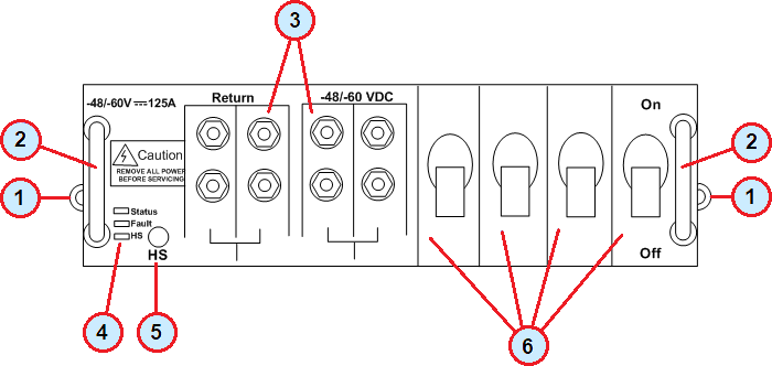
DC PEM Panel and LED Indicators on the 61000 and 41000 Chassis
|
Item |
Description |
|---|---|
|
1 |
Locking captive screws to secure the PEM in the Chassis. |
|
2 |
Handles for holding the PEM during insertion and extraction. |
|
3 |
Terminal blocks: -48/-60 VDC and Return. Each terminal block has 4 terminal studs. |
|
4 |
PEM LEDs. |
|
5 |
Hot-Swap button used to start the hot-swap sequence. |
|
6 |
4 x 50A circuit breakers. |
PEM LEDs
|
Item |
Description |
|---|---|
|
Status |
|
|
Fault |
|
|
HS (Hot swap) |
|