19000 / 29000 Appliances Hardware
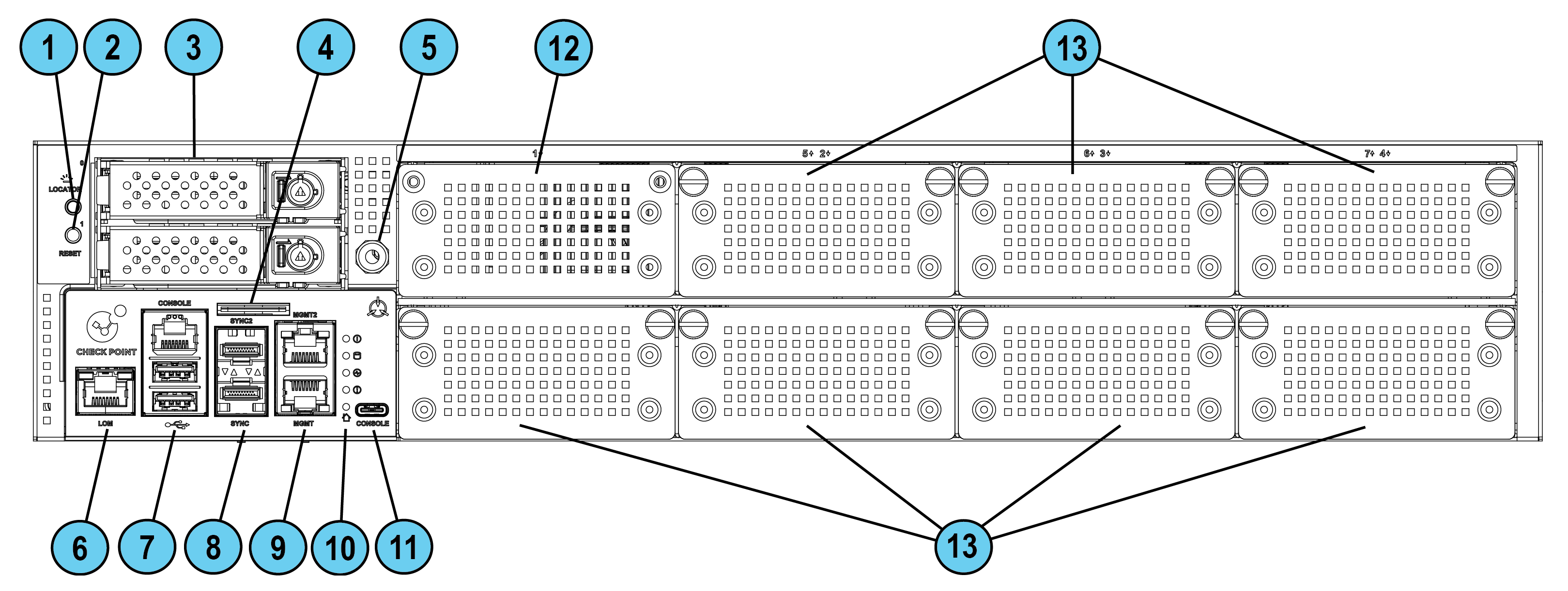
Front Panel
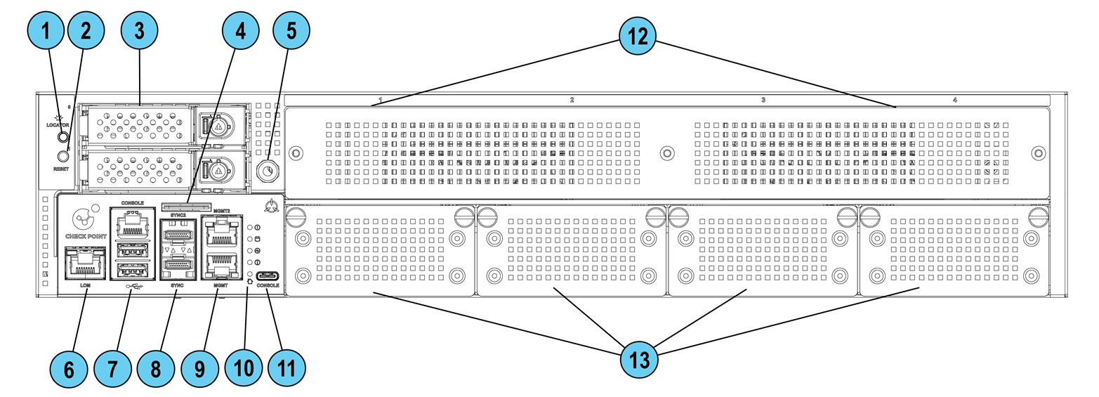
Front Panel LEDs
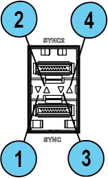
Synchronization Port LEDs
|
Item |
Component |
Description |
|---|---|---|
|
1 |
Port activity LED (bottom port SYNC) |
|
|
2 |
Port activity LED (top port SYNC2) |
|
|
3 |
Link Speed LED (bottom port SYNC) |
|
|
4 |
Link Speed LED (top port SYNC2) |
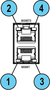
Management Port LEDs
|
Item |
Component |
Description |
|---|---|---|
|
1 |
Port activity LED (bottom port MGMT) |
|
|
2 |
Port activity LED (top port MGMT2) |
|
|
3 |
Link Speed LED (bottom port MGMT) |
|
|
4 |
Link Speed LED (top port MGMT2) |
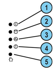
System LEDs
|
Item |
Icon |
Component |
Description |
|---|---|---|---|
|
1 |
|
System power |
|
|
2 |
|
Storage device activity |
|
|
3 |
|
Power supply status |
|
|
4 |
|
Alert |
|
|
5 |
|
Location beacon |
You can turn on / off the Location Beacon LED in these ways:
|


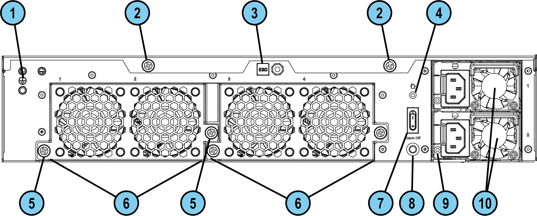
Cooling Fan Units Naming Convention
When you check the hardware sensors in the Gaia Portal or Gaia Clish, note that the cooling fans use a different naming convention.
Use this table to identify each of the 8 fans:
|
Gaia Portal |
CLI |
|---|---|
|
Fan 1 Inlet |
Fan1_IN |
|
Fan 1 Outlet |
Fan1_OUT |
|
Fan 2 Inlet |
Fan2_IN |
|
Fan 2 Outlet |
Fan2_OUT |
|
Fan 3 Inlet |
Fan3_IN |
|
Fan 3 Outlet |
Fan4_OUT |
|
Fan 4 Inlet |
Fan4_IN |
|
Fan 4 Outlet |
Fan4_OUT |
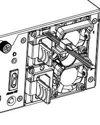
Installing the Power Cable Restraint
You can use the power cable restraint to prevent accidental removal of the power cable.
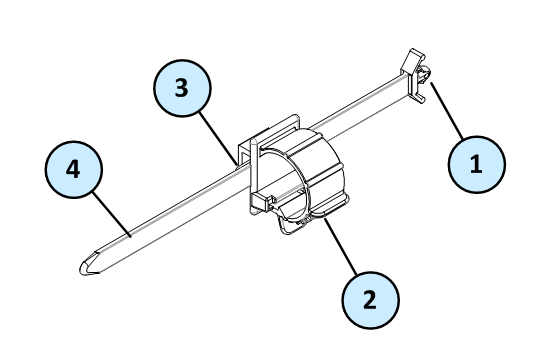
|
Item |
Description |
|---|---|
|
1 |
Restraint anchor |
|
2 |
Cable loop |
|
3 |
Restraint strip tab |
|
4 |
Restraint strip |
|
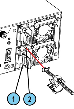
Item |
Description |
|---|---|
|
1 |
Power supply inlet |
|
2 |
Restraint strip slot |
To install the power cable restraint:
-
If a power cable is connected to the power supply inlet, disconnect it.
-
Find the restraint strip slot on top of the power supply inlet.
-
Make sure that the cable loop on the restraint faces the power supply inlet.
-
Insert the restraint strip anchor into the slot until it snaps and locks.
-
Connect the power cable to the power supply inlet.
-
Pull the restraint tab to the side to move the cable loop on the restraint strip.
-
Move the cable loop until you can wrap it around the power cable as shown in the next figure.
-
Insert the open side of the cable loop into the loop slot until it is tight against the power cable.
-
Make sure the cable loop is secured and the power cable cannot be removed.
Lights Out Management
The Check Point Lights Out Management (LOM) card lets you use a dedicated management channel to remotely control Check Point appliances. Lights Out Management can also work when the appliance is turned off or does not respond. However, the appliance must be connected to a power source.
For more information about Lights Out Management, see the Lights Out Management (LOM) HTML5-based Card Administration Guide.
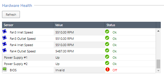
Dual Redundant BIOS
To ensure resilience in the event of a BIOS failure, 19100 / 19200 / 29100 / 29200 Appliances are equipped with dual redundant BIOS images.
If an appliance encounters a BIOS failure, it boots up from a recovery, read-only BIOS image that enables full functionality of the appliance.
These notifications appear in the event of a BIOS failure:
-
The appliance's Alert LED on the front panel blinks red.
-
The Gaia Portal > Maintenance > Hardware Health page shows that the BIOS sensor is Invalid and its status is Off.
Example (from a 29100 appliance):
-
An SNMP trap message is sent (if the
biosFailuretrap was configured in the Gaia Portal or Gaia Clish).Example:
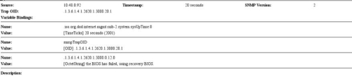
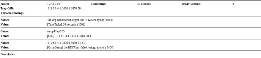
To recover from a BIOS failure, see sk108517 or contact Check Point Support. The appliance is fully functional until the BIOS recovery is completed. Note that it can take a few minutes for it to boot in BIOS recovery mode.
PSU Configuration and Monitoring
These are the supported PSU configurations for the appliance models and PSU types:
|
|
Important - All PSUs on an appliance must be of the same type: either all AC or all DC. |

When a PSU functions correctly:
-
The PSU LED is green
-
The Alert LED is not blinking due to a PSU issue (though it might still be blinking due to other errors)
-
There is no SNMP alarm
When a PSU does not function correctly:
-
The PSU LED is amber
-
The Alert LED is blinking due to a PSU issue
-
An SNMP alarm is sent.
To monitor the PSUs in the CLI:
-
Connect to the command line on the appliance.
-
Log in to Gaia Clish.
-
Run:
show sysenv psExample output from a 29100 appliance:
Hardware Information

Name              Value   Unit      Type    Status   Maximum   Minimum
Power Supply #1   Up      Up/Down   Power   0        Up        Down
Power Supply #2   Up      Up/Down   Power   0        Up        Down
Where:
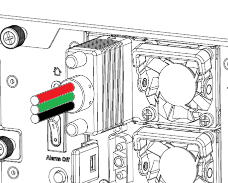
DC Power Connections
When your appliance uses a DC PSU, make sure to follow these instructions.
To connect DC power wires to a DC PSU connector:
-
Connect the GREEN wire to the ground terminal.
-
Connect the RED wire to the 36-46/46-72V pin on the DC power source.
-
Connect the BLACK wire to the return pin on the DC power source.
For further instructions, refer to the Installing and Removing DC Power Supply Units guide.
|
|
Important - This product must be powered by a UL Listed DC power source, rated 36-46/46-72Vdc, 35/40A minimum, Tmax=40°C, and the maximum operating altitude of 5000m. The wire requirements: 8 AWG, 40A minimum, 72V minimum. |
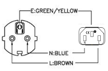
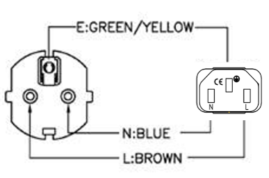
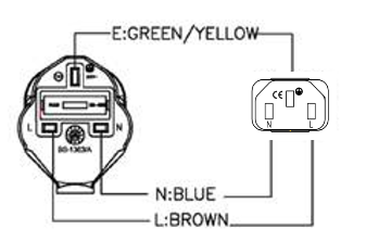
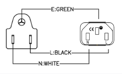
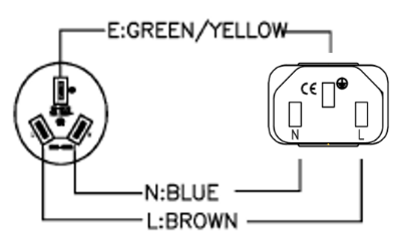
AC Power Cords
The supplied AC power cords are specific to the geographical region.
These are some of the available power cords.
|
Region |
Plug |
Connector |
Cable |
Diagram |
|---|---|---|---|---|
|
EU |
QP-004, 16A 250V~ |
QP-007, 10A 250V~ |
HO5VV-F 3G 0.75mm2 |
|
|
Australia |
QP-003, 10A 250V~ |
QP-007, 10A 250V~ |
HO5VV-F 3G 0.75mm2 |
|
|
UK |
QP-026, 10A 250V~ |
QP-007, 10A 250V~ |
HO5VV-F 3G 0.75mm2 |
|
|
US |
QP-02, 10A 125V~ |
QP-007, 10A 125V~ |
SJT 18AWG 3C 105oC |
|
|
US |
QP-02, 15A 125V~ |
QP-007, 15A 125V~ |
SJT 14AWG 3C 105oC |
|
|
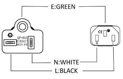
US |
QP-055, 15A 125V~ |
QP-007, 15A 125V~ |
SJT 14AWG 3C 105oC |
|
|
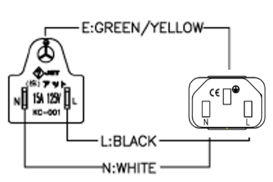
Japan |
QP-005, 10A 250V~ |
QP-007, 10A 250V~ |
HO5VV-F 3G 0.75mm2 |
|
|
India |
QP-013, 16A 250V~ |
QP-007, 10A 250V~ |
3INR 3G 0.75mm2 |
|
|
China |
QP-012, 10A 250V~ |
QP-007, 10A 250V~ |
VCTF 3G 2mm2 |
|
|
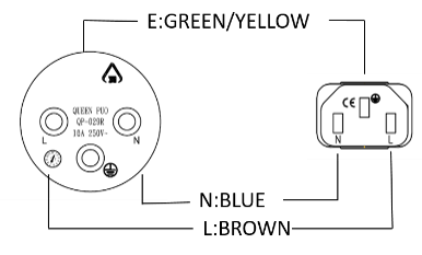
Israel |
QP-029R, 16A 250V~ |
QP-007, 10A 250V~ |
HO5VV-F 3G 0.75mm2 |
|
|
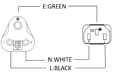
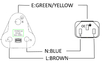
South Africa |
YP-80, 16A 250V~ |
QP-007, 10A 250V~ |
HO5VV-F 3G 0.75mm2 |
|
|
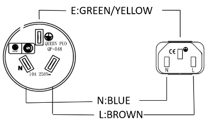
Argentina |
QP-048, 10A 250V~ |
QP-007, 10A 250V~ |
HO5VV-F 3G 0.75mm2 |
|

Replacing and Upgrading Components
The appliances have parts that you can easily replace to minimize downtime.
There are also components that you can install to upgrade the appliance.
These parts and components can be used with the appliance:
-
Telescopic rails
-
Line cards
-
Transceivers
-
AC and DC power supply units
-
Storage devices
-
System memory
-
Cooling fan units
-
Lights Out Management - In 19100 Base / 19200 Base / 29100 Base / 29200 Base appliances, the LOM Card is optional.
For more information about how to install these parts and components, see the appliance Home Page sk180520.
|
|
Warning - Unless directed to do so by Check Point Software Technologies Ltd., you are prohibited by warranty and support agreements to replace any parts. |
