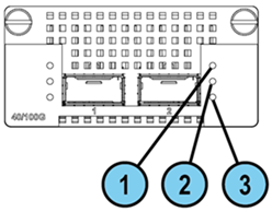
40/100 Gb Line Card (QSFP28)
This section uses these abbreviations:
|
Full Name |
Description |
Abbreviation |
|---|---|---|
|
2-Port Single-Width 10/25/40/100G QSFP28 Card |
A single-width new acceleration NIC with 4 SFP28 ports that support 10/25G throughput. |
100G Card |
|
10/25/40/100G QSFP28 Port |
Port type on the single-width NIC. |
100G Port |
These appliance models use the 2-Port Single-Width 10/25/40/100G QSFP28 Card:
Line Card Slot Population
Follow the instructions in Appendix - NIC Slot Population Guidelines for the preferred placement of this line card inside 29100 and 29200 appliances.
Installing and Removing Expansion Line Cards
See the relevant Getting Started Guide for your model (sk96246).
-
Turn off the Appliance.
-
Remove the power cords from the Power Supply Units.
-
Loosen the screws on the dummy panel on the front of the Appliance.
-
Remove the dummy panel.
-
Insert the Expansion Line Card into the expansion slot.
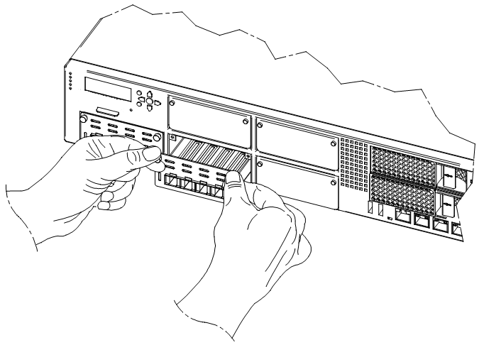
-
Push until the card clicks into position.

Note - Make sure the card is firmly inserted on all sides and that the Expansion Line Card panel is flat against the appliance's front panel.
-
Tighten the screws on the Expansion Line Card.
-
Turn on the Appliance.
See the Getting Started Guide for your model (sk96246).
-
Turn off the Appliance.
-
Remove the power cords from the Power Supply Units.
-
Loosen the captive screws on the Expansion Line Card.
-
Holding the screws, pull the Expansion Line Card out of the expansion slot.
-
Put the dummy panel on the Expansion Line Card.
-
Tighten the screws on the dummy panel.
-
Turn on the Appliance.
Configuring and Monitoring the 100G Ports
See the LightSpeed 10/25/40/100G QSFP28 Ports Administration Guide.
Mapping of 40/100G Ports and Interface Names in Gaia OS
-
In Gaia OS, port names of the installed cards start from the name "
eth<X>-01".If a card has several ports, then the port names are from
eth<X>-01toethX-0<Y>, where:-
<X>is the slot number (see the slot diagram in the corresponding section for your appliance model). -
<Y>is the port number on the card.
Examples:
eth1-01,eth3-02 -
-
Non-Maestro configuration refers to the connection of Security Appliances directly to your network and to the Check Point Management Server.
-
Maestro configuration refers to the connection of Security Appliances to a Maestro Orchestrator that in turn connects to your network and to the Check Point Management Server.
To connect to Maestro Orchestrators, you must use only the 100G Ports.
It is not supported to connect other ports to Orchestrators.
It is not necessary to remove other cards from the appliance.
The appliance ignores other cards when it operates as a Maestro Security Group Member.
|
|
Important - You must follow the guidelines in sk181465 to insert the line cards in a specific order. |

Slot Diagram for Line Cards on the Front Panel (from left to right, from bottom to top):
|
|
5 |
6 |
7 |
|
1 |
2 |
3 |
4 |
Interface Names in Gaia OS:
Note - The table below shows the possible slot population with 100G Cards. For the default configuration, refer to Check Point Product Catalog.
(*) If there are two Maestro Orchestrators on a Maestro Site, then you must connect each 100G Card on a Security Appliance to each Orchestrator on the same Site.
Important - You can connect a maximum of two 100G Cards at the same time to each Orchestrator.
Example for two 100G Cards in Slot 1 and Slot 2:
-
The first port on the first card (Slot 1) connects to one of the Downlink ports on the first Orchestrator
-
The second port on the first card (Slot 1) connects to one of the Downlink ports on the second Orchestrator
-
The first port on the second card (Slot 2) connects to one of the Downlink ports on the first Orchestrator
-
The second port on the second card (Slot 2) connects to one of the Downlink ports on the second Orchestrator
|
|
Important - You must follow the guidelines in sk181465 to insert the line cards in a specific order. |
Slot Diagram for Line Cards on the Front Panel (from left to right, from bottom to top):
|
|
5 |
6 |
7 |
|
1 |
2 |
3 |
4 |
Interface Names in Gaia OS:
Note - The table below shows the possible slot population with 100G Cards. For the default configuration, refer to Check Point Product Catalog.
(*) If there are two Maestro Orchestrators on a Maestro Site, then you must connect each 100G Card on a Security Appliance to each Orchestrator on the same Site.
Important - You can connect a maximum of two 100G Cards at the same time to each Orchestrator.
Example for two 100G Cards in Slot 1 and Slot 2:
-
The first port on the first card (Slot 1) connects to one of the Downlink ports on the first Orchestrator
-
The second port on the first card (Slot 1) connects to one of the Downlink ports on the second Orchestrator
-
The first port on the second card (Slot 2) connects to one of the Downlink ports on the first Orchestrator
-
The second port on the second card (Slot 2) connects to one of the Downlink ports on the second Orchestrator
Slot Diagram for Line Cards on the Front Panel (from left to right):
|
Not Used |
|||
|
1 |
2 |
3 |
4 |
Interface Names in Gaia OS:
Note - The table below shows the possible slot population with 100G Cards. For the default configuration, refer to Check Point Product Catalog.
(*) If there are two Maestro Orchestrators on a Maestro Site, then you must connect each 100G Card on a Security Appliance to each Orchestrator on the same Site.
Important - You can connect a maximum of two 100G Cards at the same time to each Orchestrator.
Example for two 100G Cards in Slot 1 and Slot 2:
-
The first port on the first card (Slot 1) connects to one of the Downlink ports on the first Orchestrator
-
The second port on the first card (Slot 1) connects to one of the Downlink ports on the second Orchestrator
-
The first port on the second card (Slot 2) connects to one of the Downlink ports on the first Orchestrator
-
The second port on the second card (Slot 2) connects to one of the Downlink ports on the second Orchestrator
(*) You can connect all available 100G Ports on a Security Appliance to Maestro Orchestrators on the Maestro Site.
-
The first 100G Card connects to each Orchestrator on the same Site:
-
The first port on the card connects to one of the Downlink ports on the first Orchestrator
-
The second port on the card connects to one of the Downlink ports on the second Orchestrator
-
-
The second 100G Card connects to each Orchestrator on the same Site:
-
The first port on the card connects to another Downlink port on the first Orchestrator
-
The second port on the card connects to another Downlink port on the second Orchestrator
-
Slot Diagram for Line Cards on the Front Panel (from left to right):
|
Not Used |
|||
|
1 |
2 |
3 |
4 |
Interface Names in Gaia OS:
Note - The table below shows the possible slot population with 100G Cards. For the default configuration, refer to Check Point Product Catalog.
(*) If there are two Maestro Orchestrators on a Maestro Site, then you must connect each 100G Card on a Security Appliance to each Orchestrator on the same Site.
Important - You can connect a maximum of two 100G Cards at the same time to each Orchestrator.
Example for two 100G Cards in Slot 1 and Slot 2:
-
The first port on the first card (Slot 1) connects to one of the Downlink ports on the first Orchestrator
-
The second port on the first card (Slot 1) connects to one of the Downlink ports on the second Orchestrator
-
The first port on the second card (Slot 2) connects to one of the Downlink ports on the first Orchestrator
-
The second port on the second card (Slot 2) connects to one of the Downlink ports on the second Orchestrator
Slot Diagram for the Front Panel (from left to right):
|
1 |
2 |
On-board ports (x4) |
On-board ports (x4) |
Interface Names in Gaia OS:
(*) If there are two Maestro Orchestrators on a Maestro Site, then you must connect each 100G Card on a Security Appliance to each Orchestrator on the same Site.
Important - You can connect a maximum of two 100G Cards at the same time to each Orchestrator.
Example for two 100G Cards in Slot 1 and Slot 2:
-
The first port on the first card (Slot 1) connects to one of the Downlink ports on the first Orchestrator
-
The second port on the first card (Slot 1) connects to one of the Downlink ports on the second Orchestrator
-
The first port on the second card (Slot 2) connects to one of the Downlink ports on the first Orchestrator
-
The second port on the second card (Slot 2) connects to one of the Downlink ports on the second Orchestrator
Slot Diagram for the Front Panel (from left to right):
|
1 |
On-board ports (x4) |
On-board ports (x8) |
Interface Names in Gaia OS:
(*) If there are two Maestro Orchestrators on a Maestro Site, then you must connect each 100G Card on a Security Appliance to each Orchestrator on the same Site:
-
The first port on the card connects to one of the Downlink ports on the first Orchestrator
-
The second port on the card connects to one of the Downlink ports on the second Orchestrator
Slot Diagram for the Front Panel (from left to right):
|
On-board ports (x4) |
1 |
Interface Names in Gaia OS: