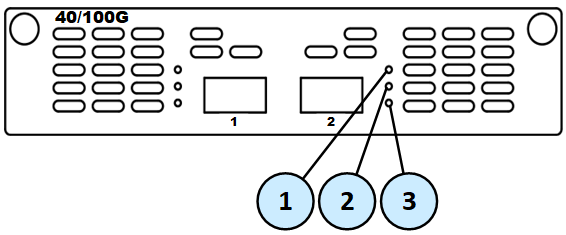
2-Port Dual-Width 10/25/40/100G QSFP28 Card
This section uses these abbreviations:
|
Full Name |
Description |
Abbreviation |
|---|---|---|
|
2-Port Dual-Width 10/25/40/100G QSFP28 Card |
A dual-width NIC that takes two slots in the appliance (specific pairs of slots). |
100G Card |
|
10/25/40/100G QSFP28 Port |
Port type on the dual-width NIC. |
100G Port |
These appliance models use the 2-Port Dual-Width 10/25/40/100G QSFP28 Card:
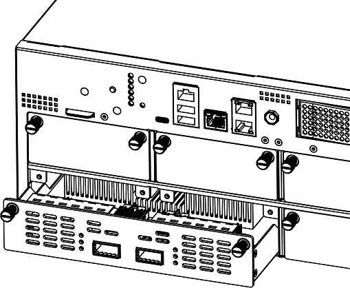
Installing a 2-Port Dual-Width 10/25/40/100G QSFP28 Card
Note - In the MLS400 model, these ports are built-in.
-
Turn off the Appliance.
See the Getting Started Guide for your model:
-
Remove the power cords from the Power Supply Units.
-
Loosen the screws on two horizontally adjacent dummy panels on the front of the Appliance.

Important - See the mapping of supported adjacent slots.
-
Remove the two horizontally adjacent dummy panels.
Example for a 1U Appliance:
-
Remove the slot divider.
In a 1U Appliance
In 2U and 3U Appliances
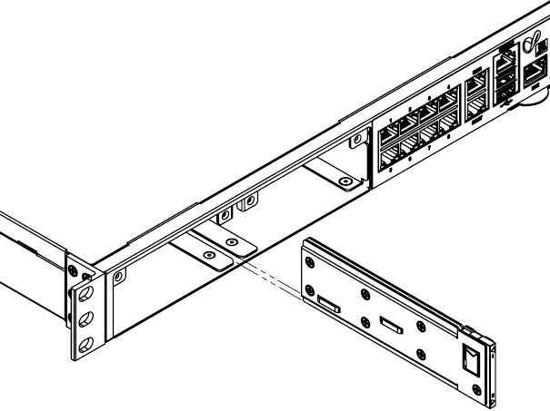
-
Squeeze the recessed tabs on the front left side of the slot divider to release the latching mechanism.
-
Pull the slot divider to remove it.
-
Insert a finger into the slot divider hole.
-
Push the latch trigger with your finger tab inside the hole to release the latching mechanism.
-
Pull the slot divider with your finger to remove it.
Example:
Example for a 3U Appliance:
-
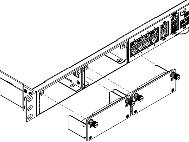
-
Insert the 100G Card into the expansion slot.
Example for a 3U Appliance:
-
Push until the card clicks into position.

Note - Make sure the card is firmly inserted on all sides and that the 100G Card front panel is flat against the appliance's front panel.
-
Tighten the screws on the 100G Card.
-
Turn on the Appliance.
See the Getting Started Guide for your model:
Removing a 2-Port Dual-Width 10/25/40/100G QSFP28 Card
Note - In the MLS400 model, these ports are built-in.
-
Turn off the Appliance.
See the Getting Started Guide for your model:
-
Remove the power cords from the Power Supply Units.
-
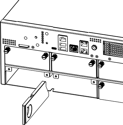
Loosen the captive screws on the 100G Card.
-
Holding the screws, pull the 100G Card out of the expansion slot.
Example for a 3U Appliance:
-
Insert the slot divider and push it until its latching mechanism clicks.
Example for a 1U Appliance:
Example for a 3U Appliance:
-
Put the two dummy panels on the expansion slot.
Example for a 1U Appliance:
-
Tighten the screws on each dummy panel.
-
Turn on the Appliance.
See the Getting Started Guide for your model:
Configuring and Monitoring the 100G Ports
-
For QLS800, QLS650, QLS450, QLS250, and MLS200 Appliances:
See the LightSpeed 10/25/40/100G QSFP28 Ports Administration Guide.
-
For 28000, 26000, 16200, 16000, 7000, and 6900 Appliances:
See sk181064.
Mapping of 100G Ports and Interface Names in Gaia OS
-
The 100G Card takes two consecutive interface names in Gaia OS.
In addition, the 100G Card reserves the second NIC slot's numbering.
See the slot diagram in the corresponding section for your appliance model.
If this card is installed in a LightSpeed Appliance in Slots 1+2 of the appliance, then in Gaia OS, the names of ports are
eth1-01andeth1-02.If this card is installed in a LightSpeed Appliance in Slots 3+4 of the appliance, then in Gaia OS, the names of ports are
eth3-01andeth3-02. -
You can move the installed cards from their default slots to different slots.
The 100G Card supports only specific pairs of slots.
-
Non-Maestro configuration refers to the connection of Security Appliances directly to your network and to the Check Point Management Server.
-
Maestro configuration refers to the connection of Security Appliances to a Maestro Orchestrator that in turn connects to your network and to the Check Point Management Server.
To connect to Maestro Orchestrators, you must use only the 100G Ports.
It is not supported to connect other ports to Orchestrators.
It is not necessary to remove other cards from the appliance.
The appliance ignores other cards when it operates as a Maestro Security Group Member.
Note - On this appliance model, hardware acceleration of traffic forwarding is supported.
Slot Diagram for Line Cards on the Front Panel (from left to right, from top to bottom):
|
1 |
2 |
3 |
4 |
|
5 |
6 |
7 |
8 |
Interface Names in Gaia OS:
By default, this appliance model has these cards installed:
(*) If there are two Maestro Orchestrators on a Maestro Site, then you must connect each 100G Card on a Security Appliance to each Orchestrator on the same Site.
Important - You can connect a maximum of two 100G Cards at the same time to each Orchestrator.
Example for two 100G Cards in Slots 1 + 2 and Slots 3 + 4:
-
The first port on the first card (Slots 1 + 2) connects to one of the Downlink ports on the first Orchestrator
-
The second port on the first card (Slots 1 + 2) connects to one of the Downlink ports on the second Orchestrator
-
The first port on the second card (Slots 3 + 4) connects to one of the Downlink ports on the first Orchestrator
-
The second port on the second card (Slots 3 + 4) connects to one of the Downlink ports on the second Orchestrator
Note - On this appliance model, hardware acceleration of traffic forwarding is supported.
Slot Diagram for Line Cards on the Front Panel (from left to right):
|
1 |
2 |
3 |
4 |
Interface Names in Gaia OS:
By default, this appliance model has these cards installed:
(*) If there are two Maestro Orchestrators on a Maestro Site, then you must connect each 100G Card on a Security Appliance to each Orchestrator on the same Site.
-
The first port on the card connects to one of the Downlink ports on the first Orchestrator
-
The second port on the card connects to one of the Downlink ports on the second Orchestrator
Note - On this appliance model, hardware acceleration of traffic forwarding is supported.
Slot Diagram for the Front Panel (from left to right):
|
1 |
2 |
On-board ports (x8) |
Interface Names in Gaia OS:
By default, this appliance model has these cards installed and ports:
(*) If there are two Maestro Orchestrators on a Maestro Site, then you must connect each 100G Card on a Security Appliance to each Orchestrator on the same Site.
-
The first port on the card connects to one of the Downlink ports on the first Orchestrator
-
The second port on the card connects to one of the Downlink ports on the second Orchestrator
Note - On this appliance model, hardware acceleration of traffic forwarding is not supported.
Slot Diagram for Line Cards on the Front Panel (from left to right, from top to bottom):
|
1 |
2 |
3 |
4 |
|
5 |
6 |
7 |
8 |
This appliance model supports a maximum of four cards.
Interface Names in Gaia OS:
(*) If there are two Maestro Orchestrators on a Maestro Site, then you must connect each 100G Card on a Security Appliance to each Orchestrator on the same Site.
Important - You can connect a maximum of two 100G Cards at the same time to each Orchestrator.
Example for two 100G Cards in Slots 1 + 2 and Slots 3 + 4:
-
The first port on the first card (Slots 1 + 2) connects to one of the Downlink ports on the first Orchestrator
-
The second port on the first card (Slots 1 + 2) connects to one of the Downlink ports on the second Orchestrator
-
The first port on the second card (Slots 3 + 4) connects to one of the Downlink ports on the first Orchestrator
-
The second port on the second card (Slots 3 + 4) connects to one of the Downlink ports on the second Orchestrator
Note - On this appliance model, hardware acceleration of traffic forwarding is not supported.
Slot Diagram for Line Cards on the Front Panel (from left to right):
|
1 |
2 |
3 |
4 |
This appliance model supports a maximum of two cards.
Interface Names in Gaia OS:
(*) If there are two Maestro Orchestrators on a Maestro Site, then you must connect each 100G Card on a Security Appliance to each Orchestrator on the Site. You must use at least two 100G Ports.
Example:
-
The first port on the first card (Slots 1 + 2) connects to one of the Downlink ports on the first Orchestrator
-
The second port on the first card (Slots 1 + 2) connects to one of the Downlink ports on the second Orchestrator
-
The first port on the second card (Slots 3 + 3) connects to one of the Downlink ports on the first Orchestrator
-
The second port on the second card (Slots 3 + 4) connects to one of the Downlink ports on the second Orchestrator
Note - On this appliance model, hardware acceleration of traffic forwarding is not supported.
Slot Diagram on the Front Panel (from left to right):
|
1 |
2 |
On-board ports (x8) |
This appliance model supports only one card.
Interface Names in Gaia OS:
(*) If there are two Maestro Orchestrators on a Maestro Site, then you must connect the two 100G Ports on a Security Appliance to each Orchestrator on the Site:
-
The first port on the card connects to one of the Downlink ports on the first Orchestrator
-
The second port on the card connects to one of the Downlink ports on the second Orchestrator