TE2000XN Appliances Hardware
Front Panel

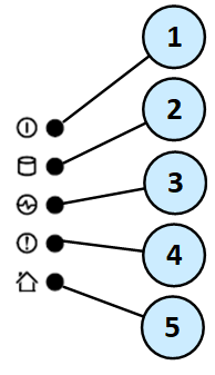
Front Panel System LEDs
|
Item |
Icon |
Component |
Description |
|---|---|---|---|
|
1 |
|
System power |
|
|
2 |
|
Storage device activity |
|
|
3 |
|
Power supply status |
|
|
4 |
|
Alert |
|
|
5 |
|
Location beacon |
Note - Turn off the Location beacon LED the same way you turned it on |


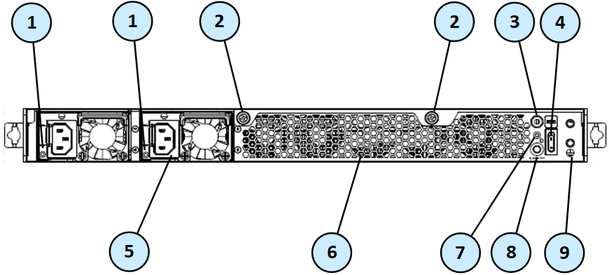
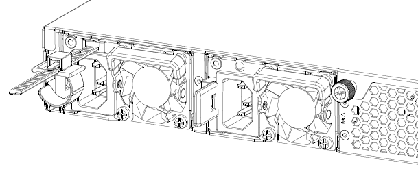
Rear Panel
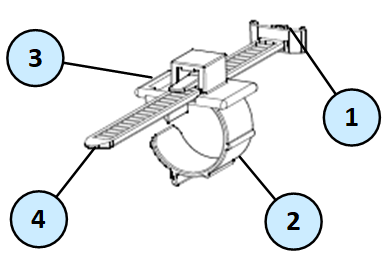
Installing the Power Cable Restraint
You can use the power cable restraint to prevent accidental removal of the power cable.
|
Item |
Description |
|---|---|
|
1 |
Restraint anchor |
|
2 |
Cable loop |
|
3 |
Restraint strip tab |
|
4 |
Restraint strip |
|
Item |
Description |
|---|---|
|
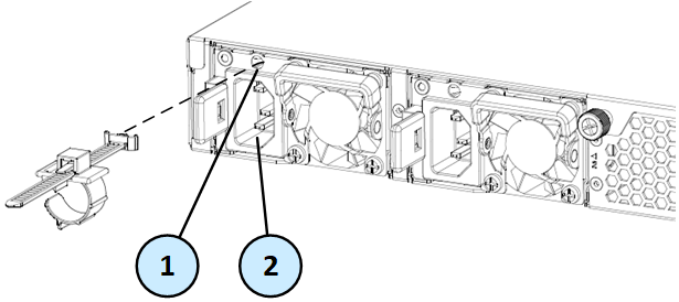
1 |
Restraint strip slot |
|
2 |
Power supply inlet |
To install the power cable restraint:
-
If a power cable is connected to the power supply inlet, disconnect it.
-
Find the restraint strip slot on top of the power supply inlet.
-
Make sure that the cable loop on the restraint faces the power supply inlet.
-
Insert the restraint strip anchor into the slot until it snaps and locks.

-
Connect the power cable to the power supply inlet.
-
Pull the restraint tab to the side to move the cable loop on the restraint strip.
-
Move the cable loop until you can put it around the power cable.
-
Insert the open side of the cable loop into the loop slot until it is tight against the power cable.
-
Make sure the cable loop is secured and the power cable cannot be removed.
Lights Out Management
The Check Point Lights Out Management (LOM) card lets you use a dedicated management channel to remotely control Check Point appliances. Lights Out Management can also work when the appliance is turned off or not responding. However, the appliance must be connected to a power source.
For more about using Lights Out Management, see the Lights Out Management (LOM) HTML5-based Card Administration Guide.
Dual Redundant BIOS
To ensure resilience in the event of a BIOS failure, appliances are equipped with dual redundant BIOS images.
If an appliance encounters a BIOS failure, it will boot up from a recovery, read-only BIOS image that enables full functionality of the appliance.
These notifications are shown in the event of a BIOS failure:
-
The appliance's Alert LED on the front panel will blink red.
-
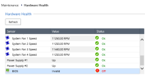
The Gaia Portal Maintenance > Hardware Health page shows that the BIOS sensor is Invalid and its status is Off.
Example:
-
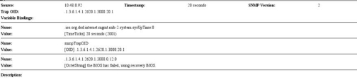
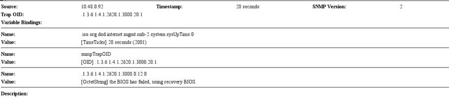
An SNMP trap message is sent (if the
biosFailuretrap was configured in the Gaia Portal or Gaia Clish).Example:

To recover from a BIOS failure, see sk108517 or contact Check Point Support. The appliance is fully functional until the BIOS recovery is completed. Note that it can take a few minutes for it to boot in BIOS recovery mode.
PSU Configuration and Monitoring
The supported PSU configurations for the appliance's PSU types:
|
|
Important - All PSUs on an appliance must be of the same type, either all AC or all DC. |

When a PSU is functioning correctly: the PSU LED is green, the Alert LED is not blinking due to a PSU issue (might still be blinking due to other errors), and there is no SNMP alarm.
When a PSU is not functioning correctly: the PSU LED is amber, the Alert LED is blinking due to a PSU issue, and an SNMP alarm is sent.
To monitor the PSUs through the CLI:
-
Connect to the command line on the appliance.
-
Log in to Gaia Clish.
-
Run:
show sysenv psSample output:
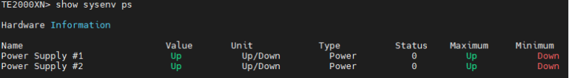
Where:
Replacing and Upgrading Components
The appliance has parts that you can easily replace to minimize downtime. There are also components that you can replace/install to repair/upgrade the appliance. These are the parts and components that can be used with the appliance:
-
Telescopic rails
-
Transceivers
-
AC and DC Power Supply Units
-
System memory
-
Lights Out Management
For more information about installing these parts and components, see the appliance home page.
Unless directed to do so by Check Point technical support, you are prohibited by warranty and support agreements from replacing any parts.
Storage Device
TE2000XN appliances are shipped with one internal storage device, and do not support a RAID configuration.