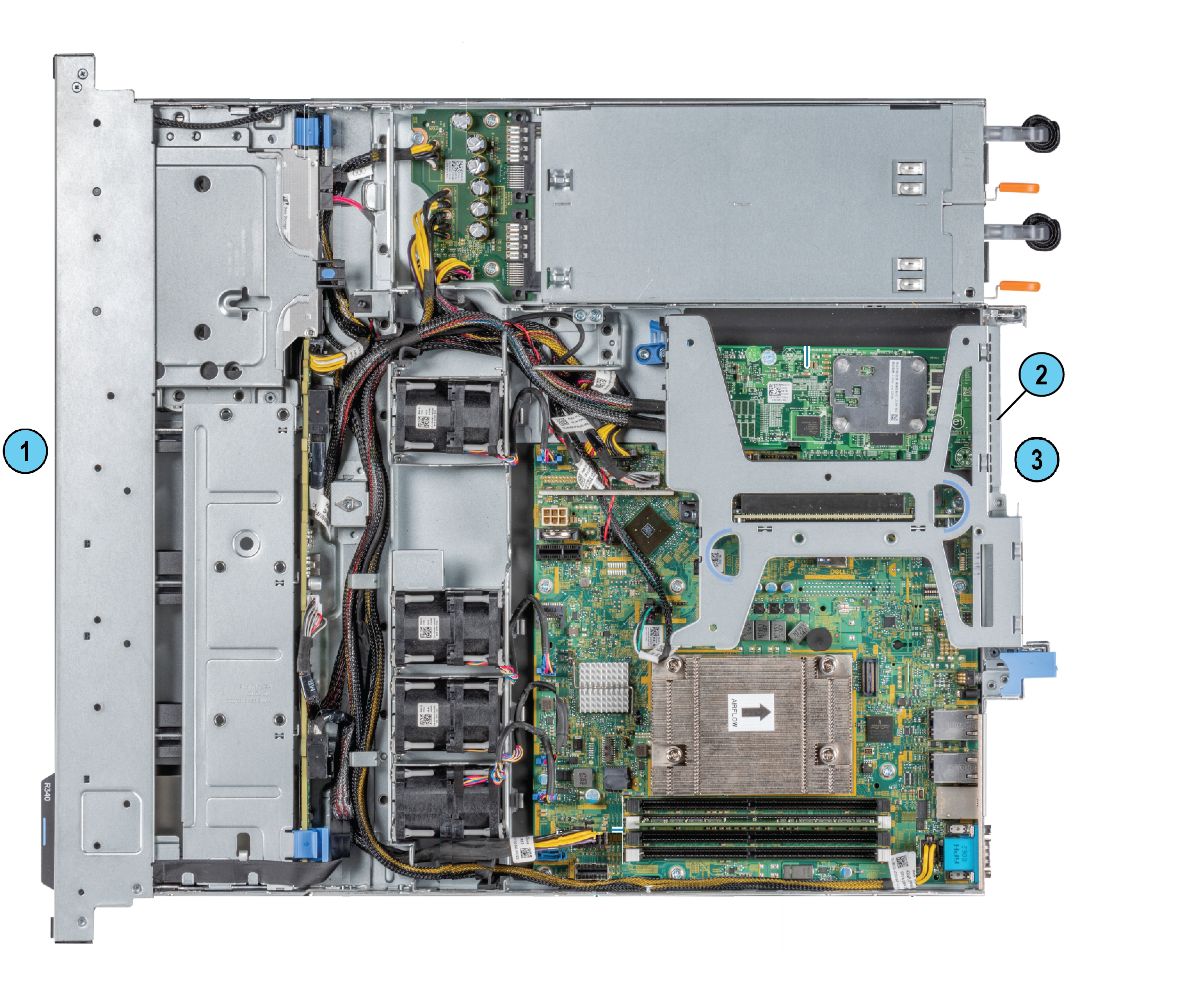
Hardware Components
|
Item |
Description |
|---|---|
|
1 |
Front panel |
|
2 |
Riser |
|
3 |
Rear panel |
Supported Expansion Line Cards
An expansion line card is an add-on card that can be inserted into an expansion slot on riser card to add enhanced functionality to the appliance through the expansion bus.
These expansion line cards are available:
-
1 Gb Ethernet
-
10 Gb Ethernet
For a list of supported line cards, see:
https://www.checkpoint.com/downloads/products/smart-1-405-410-625-5050-5150-datasheet.pdf
In the Smart-1 625 appliance there is 1 available expansion line card slot.
Procedure
Use the relevant install or replace workflow for your appliance. For each step in the workflow, follow the instructions as described in the subsequent sections of this guide.
To install a new expansion line card on Smart-1 625 appliances:
-
Prepare the appliance.
-
Remove the riser.
-
Install a new expansion line card into the riser.
-
Install the riser.
-
Reassemble the appliance.
-
Install a transceiver.
To replace an existing expansion line card on Smart-1 625 appliances:
-
Prepare the appliance.
-
Remove the riser.
-
Remove the existing expansion line card from the riser.
-
Install a new expansion line card into the riser.
-
Install the riser.
-
Reassemble the appliance.
-
Install a transceiver.
Preparing the Appliance
-
Make sure to follow the safety instructions.
- Shut down the appliance:
In Gaia Portal:
Go to Maintenance > Shut Down, and click Halt.
In Gaia Clish:
Run: halt
-
Open the retention strap that secures the power cables to the PSUs.
-
Disconnect the power cables from the AC PSUs.
-
Remove the hook-and-loop straps that hold and secure the system cables, if they interfere with the PSU removal.
-
Remove the appliance from the rack.
-
Put the Electrostatic Discharge (ESD) grounding strap on your wrist and attach the other end to a grounding point.
-
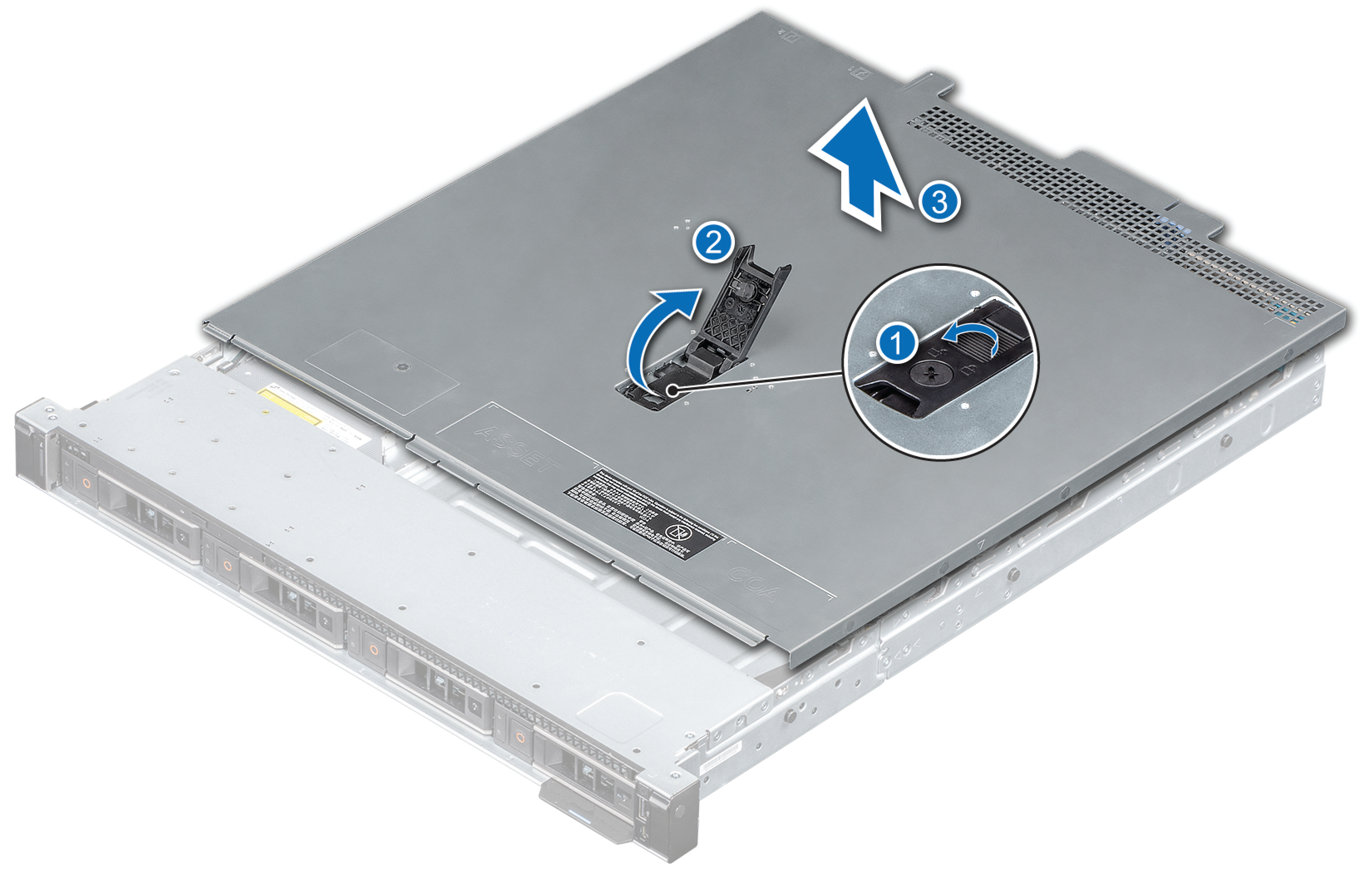
Remove the appliance cover.
-
Use a 1/4 inch flat head or a Phillips #2 screwdriver to turn the lock counter clockwise to the unlocked position (1).
-
Open the release latch until the system cover slides back (2).
-
Lift the cover from the system (3).
-
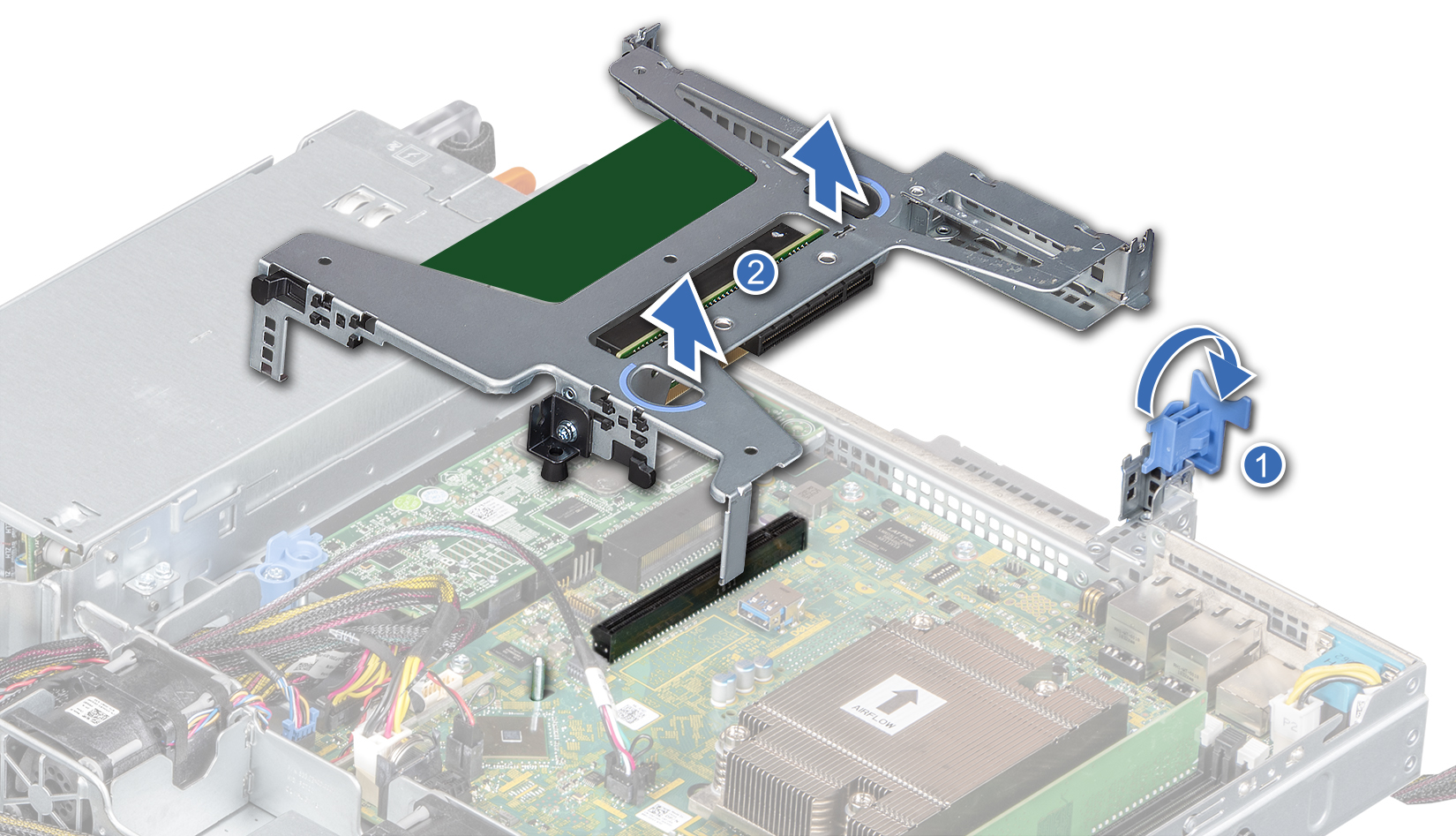
Removing the Riser
-
Open the blue expansion card riser retention latch located on the appliance (1).
-
Holding the blue touch points (2), lift the expansion card riser from the appliance.

|
Note - The illustration shows a riser with only the onboard NIC installed. |
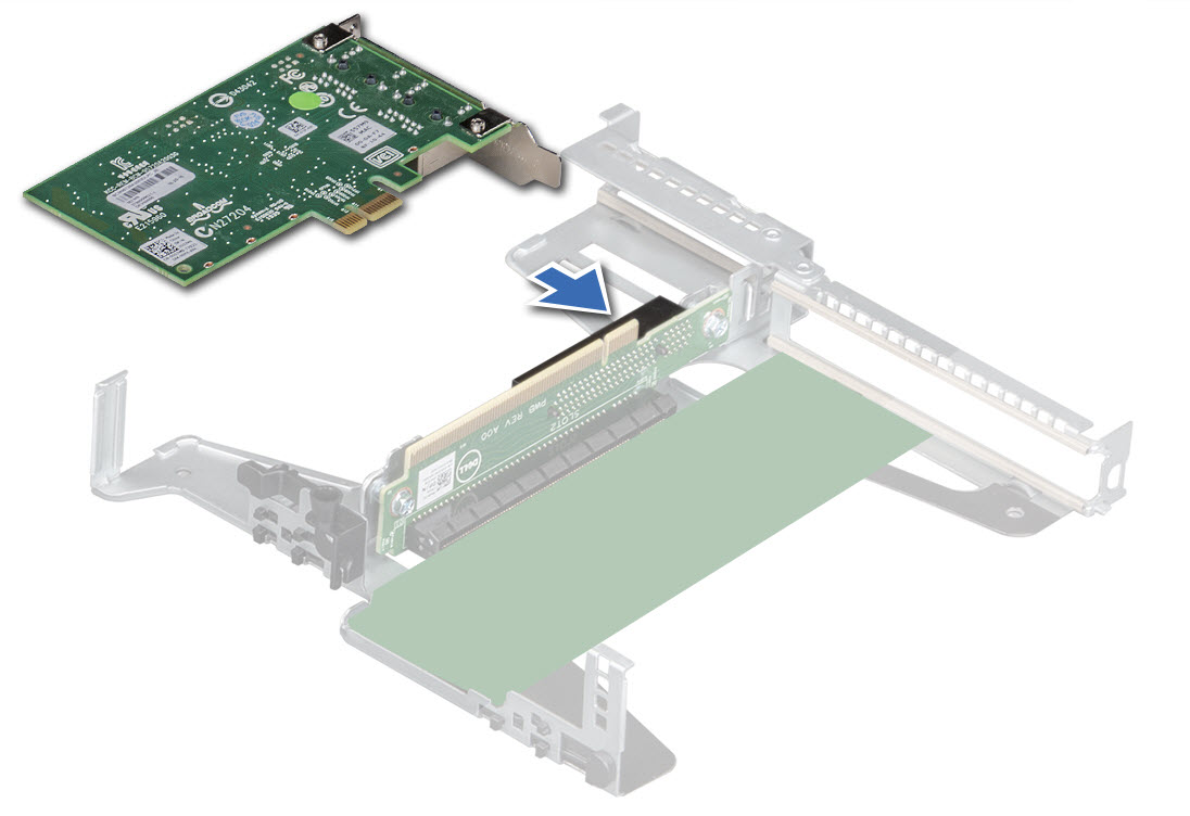
Removing an Expansion Line Card from the Riser
-
Disconnect any cables that are connected to the expansion card or riser.
-
Remove the riser.
-
Flip the riser to locate the connectors on the riser.
-
Holding the card by its edges, remove the expansion card from the riser.

Important - Do not remove the integrated onboard NIC as warranty will be void.
-
If you are removing the card permanently, install a filler bracket in the empty expansion card slot.
Note - Install a filler bracket over an empty expansion card slot to maintain Federal Communications Commission (FCC) certification of the system. The brackets also keep dust and dirt out of the system and aid in proper cooling and airflow inside the system. A filler bracket is not supplied when purchasing a pre-installed appliance.
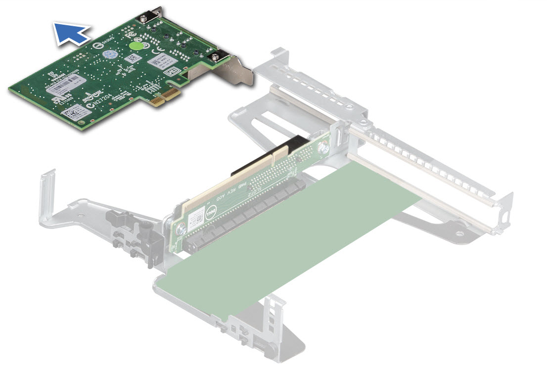
Installing an Expansion Line Card into the Riser
-
Unpack the expansion line card and prepare it for installation.
-
Remove the riser.
-
If you are installing an expansion line card for the first time, remove the filler bracket from the empty expansion slot and store it.
-
Locate the expansion line card connector on the riser.
-
Holding the expansion line card by its edges, position the card so that the card connector aligns with the connector on the riser.
-
Insert the card connector into the riser connector until the card is firmly seated.
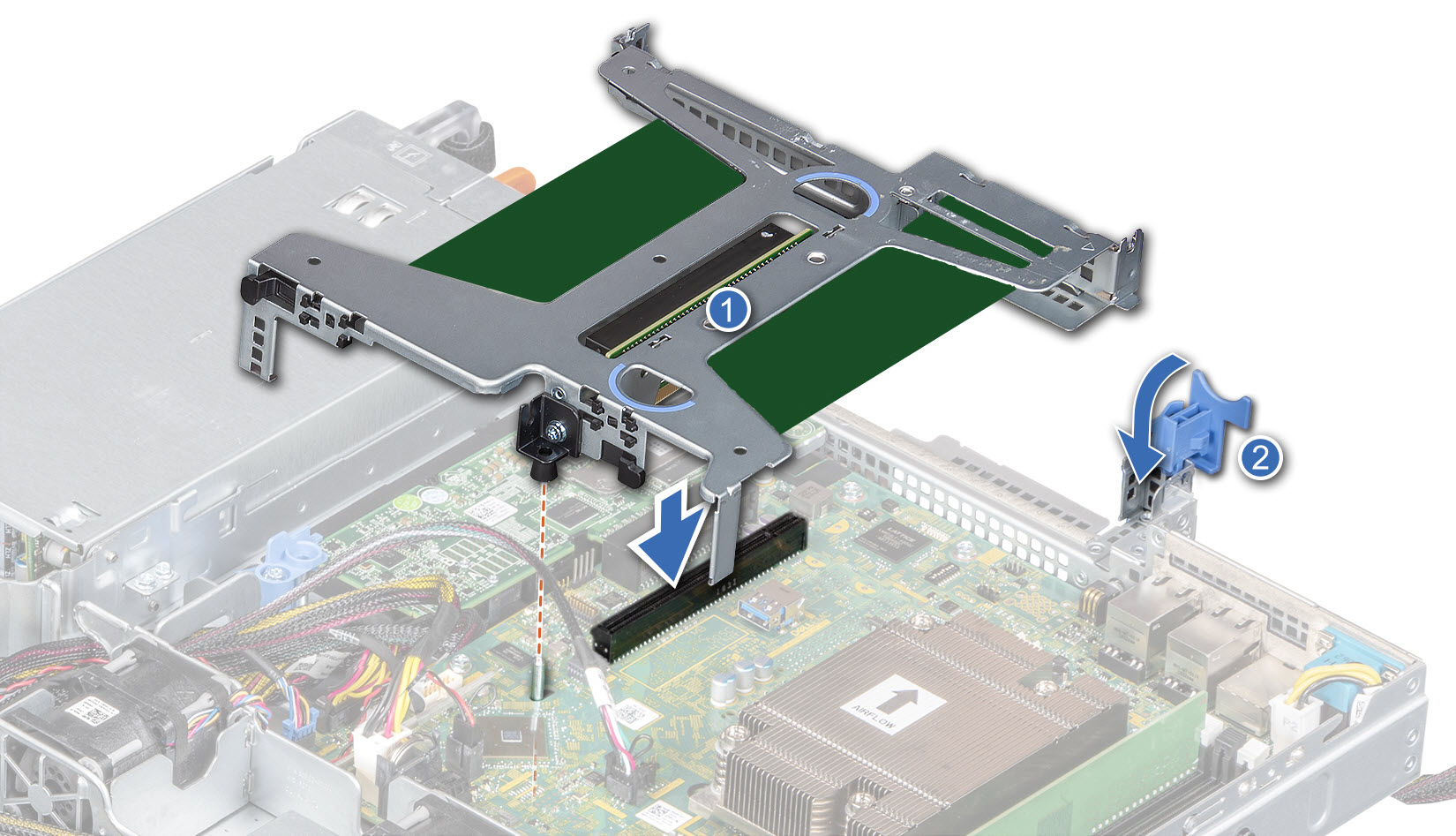
Installing the Riser
-
Open the riser latch.
- Align the following:
Guide on the riser with the guide pin on the system board.
Riser connector with the connector on the system board.
-
Lower the riser until the riser is firmly seated in the connector on the system board.
-
Close the riser latch.
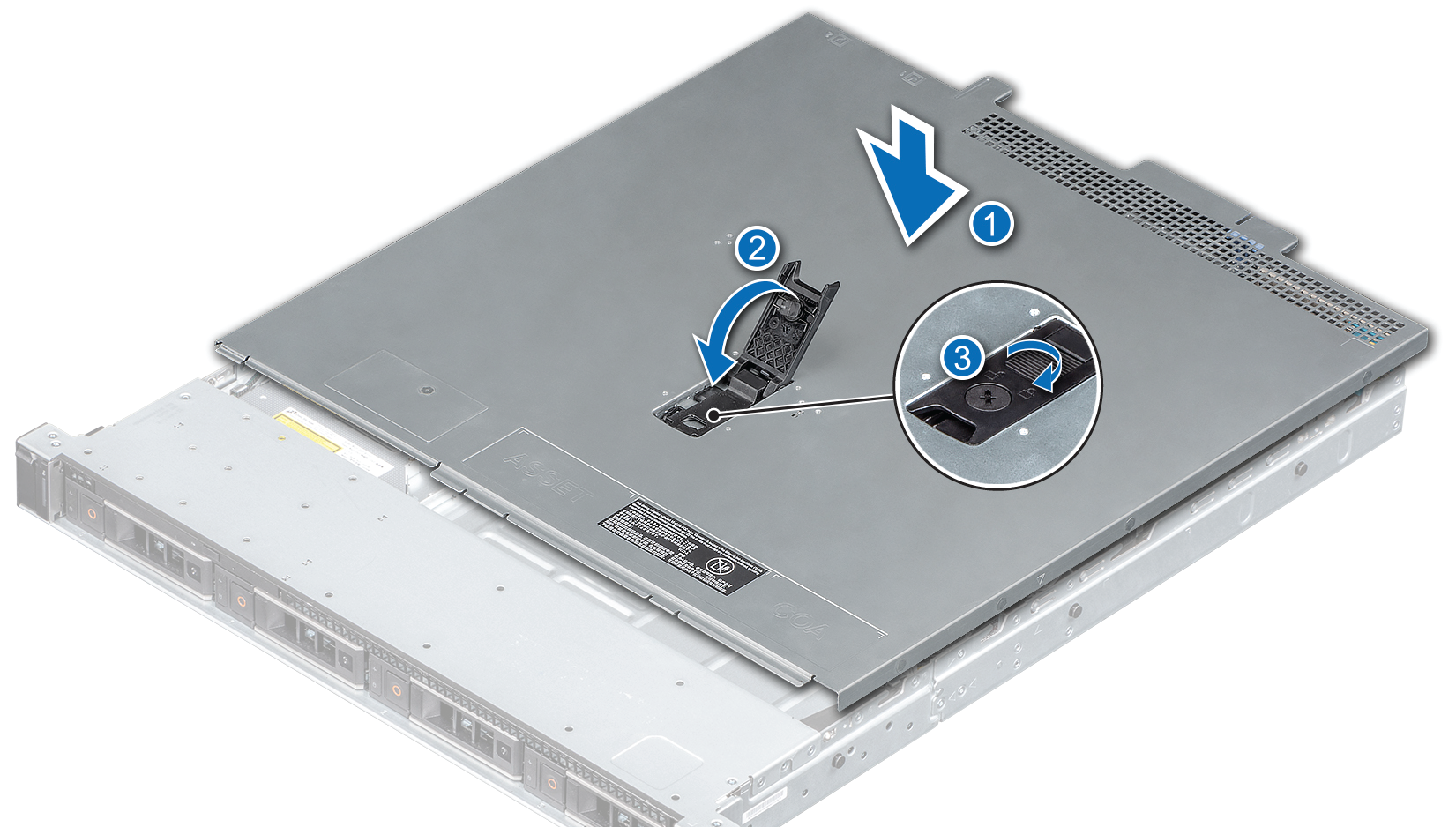
Reassembling the Appliance
Make sure that all internal cables are routed correctly and connected, and no tools or extra parts are left inside the appliance.
To reassemble the appliance:
-
Align the tabs on the cover with the guide slots on the appliance (1).
-
Close the system cover release latch (2).
-
Using a 1/4 inch flat head or Phillips #2 screwdriver, turn the lock clockwise to the lock position (3).
-
Install the appliances into the rack. See the Smart-1 625 Installing the Telescopic Rails Guide.
-
If you have transceivers for your expansion line cards, install them now. See Installing a Transceiver.
If not, install them later.
-
Connect the power cables from the AC PSUs.
-
If you opened the hook-and-loop straps, close them to secure the appliance cables.
-
Press the Power button on the front panel to turn on the Security Management appliance.
Installing a Transceiver
If your expansion line card contains removable transceivers, you can install and replace these transceivers.
For a list of supported transceivers, see:
https://www.checkpoint.com/downloads/products/smart-1-405-410-625-5050-5150-datasheet.pdf
![]()
| Item | Description |
|---|---|
|
1 |
Expansion line card with fiber optic ports |
|
2 |
Transceiver |
|
3 |
Transceiver latch |
To install a transceiver:
-
Push the transceiver into an expansion line card port until it snaps into position.
-
Turn the transceiver latch lever up to lock into the expansion line card.
-
Connect the fiber optic cable to the transceiver.
To remove a transceiver:
-
Disconnect the fiber optic cables from the transceiver.
-
Pull the latch lever down to release the transceiver.
-
Gently, pull the transceiver out of the expansion line card.