Smart-1 600-S Appliances Hardware
Front Panel
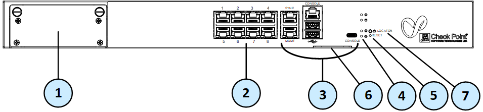
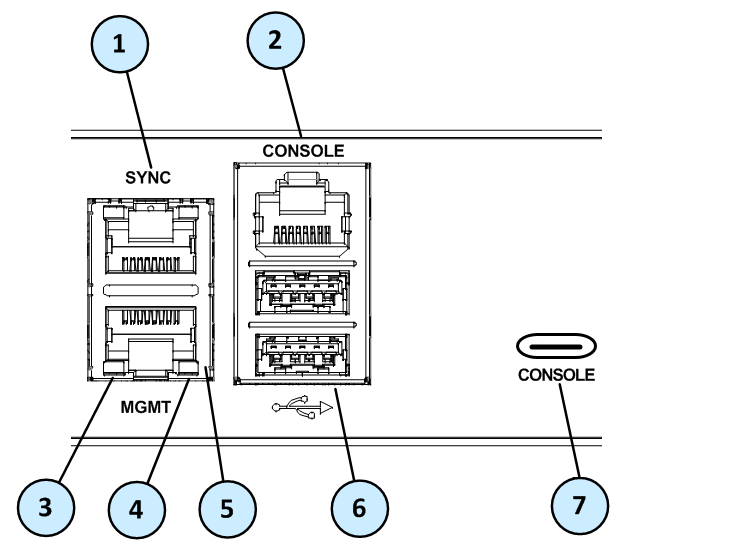
Front Panel Ports
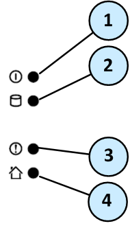
Front Panel System LEDs
System power, storage device activity, power supply status, alert, and location.
|
Item |
Icon |
Component |
Description |
|---|---|---|---|
|
1 |
|
System power |
|
|
2 |
|
Storage device activity |
|
|
3 |
|
Alert |
|
|
4 |
|
Location beacon |
Note - You can turn off the Location beacon LED from the Locator button, Gaia Portal, or Gaia Clish. |


Rear Panel

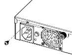
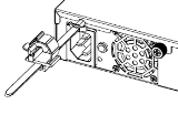
Using the Power Cable Restraint Strip
You can use the power cable restraint to prevent accidental removal of the power cable.

|
Item |
Description |
|---|---|
|
1 |
Restraint anchor |
|
2 |
Cable loop |
|
3 |
Restraint strip tab |
|
4 |
Restraint strip |
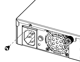
To install the power cable restraint strip:
-
If a power cable is connected to the power supply inlet, disconnect it.
-
Unscrew the screw directly above the power supply inlet.
-
Make sure the cable loop on the restraint strip faces the power supply inlet.
-
Insert the restraint strip anchor into the slot and screw it in until it locks.
-
Connect the power cable to the power supply inlet.
-
Move the cable loop on the restraint strip.
-
Move the cable loop until you can put it around the power cable.
-
Insert the open side of the cable loop into the loop slot until it is tight against the power cable.
-
Make sure the cable loop is secured and the power cable cannot be removed.

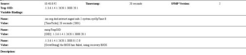
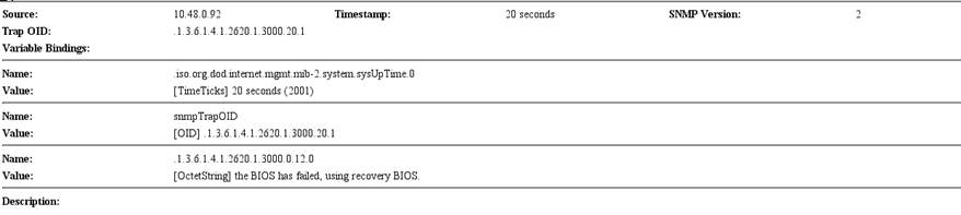
Dual Redundant BIOS
To ensure resilience in the event of a BIOS failure, Smart-1 600-S appliances are equipped with dual redundant BIOS images.
If an appliance encounters a BIOS failure, it will boot up from a recovery, read-only BIOS image that enables full functionality of the appliance.
These notifications are shown in the event of a BIOS failure:
-
The appliance's Alert LED on the front panel will blink red.
-
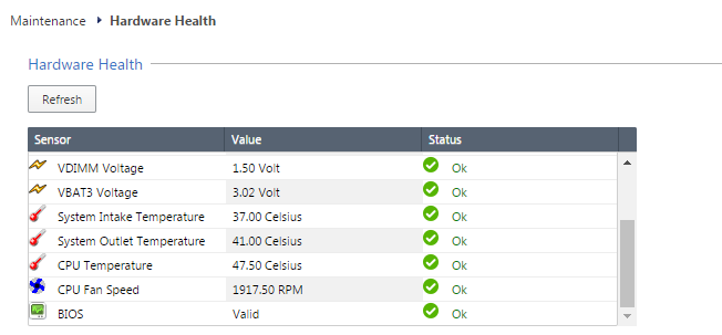
The Gaia WebUI Hardware Health window shows that the BIOS sensor is Invalid and its status is Off.
-
An SNMP trap message (if the biosFailure trap was configured in the WebUI or through clish).
To recover from a BIOS failure, see sk108517 or contact Check Point support. The appliance is fully functional until the BIOS recovery is completed.
Replacing and Upgrading Components
The Smart-1 600-S appliances have parts that you can easily replace to minimize downtime. There are also components that you can install to upgrade the appliance. These are the parts and components that can be used with the appliance:
-
Telescopic rails (optional)
-
System memory
For more information about installing these parts and components, see the Smart-1 600-S/600-M/6000-L/6000-XL home page.
Unless directed to do so by Check Point technical support, you are prohibited by warranty and support agreements from replacing any parts.