VSNext
|
|
Notes:
|
Limitations
-
The acceleration card hardware does not accelerate connections that pass through more than one Virtual Gateway.
Introduction to VSNext
Introduced in the R82 version, VSNext is an enhanced VSX mode that allows simpler configuration, easier provisioning, and a similar experience to a physical Security Gateway.
The benefits of the VSNext mode are:
-
Unified management experience between Check Point physical Security Gateways and Virtual Gateways, including the capability to manage each Virtual Gateway from a different Management Server.
-
Improves VSX provisioning performance and provisioning experience - creating, modifying, and deleting Virtual Gateways and Virtual Switches in Gaia Portal, Gaia Clish, or with Gaia REST API.
-
Management feature and API parity between Virtual Gateways (VGW) and physical Security Gateways.
|
|
Important - Installation of CPUSE packages applies to the entire ElasticXL / Maestro Security Group. |
Configuration Methods for VSNext
You can configure the required Virtual Gateways and Virtual Switches in one of these ways:
-
Gaia Portal:
 Workflow
-
Configure the required Virtual Gateways and Virtual Switches objects on the page Virtual Systems.
-
In the top filter Virtual System, select the required Virtual Gateway.
- Configure the required Gaia OS settings on the available pages in Gaia Portal.
-
-
Gaia Clish:
Available Gaia Clish commands
-
Add the required objects with these commands:
add vsnext virtual-gateway interfaces <Name of Interface> id {auto | <1-511>} one-time-password <SIC Activation Key> instances <Number of IPv4 CoreXL Firewall Instances> instances6 Number of IPv6 CoreXL Firewall Instances wait-for-task {true | false}add vsnext virtual-switch name <Name of Virtual Switch> id <ID of Virtual Switch> wait-for-task {true | false}add vsnext virtual-link virtual-gateway <ID of Virtual Gateway> virtual-switch <ID of Virtual Switch> wrp-id <0-63> -
Configure the required settings with these commands:
set vsnext interfaces <Name of Interface> virtual-system <ID of Virtual Gateway>set vsnext corexl-instances virtual-gateway <ID of Virtual Gateway> ipv4-instances Number of IPv4 CoreXL Firewall Instances wait-for-task {true | false}set vsnext corexl-instances virtual-gateway <ID of Virtual Gateway> ipv6-instances Number of IPv6 CoreXL Firewall Instances wait-for-task {true | false}set vsnext corexl-instances virtual-gateway <ID of Virtual Gateway> ipv4-instances Number of IPv4 CoreXL Firewall Instances ipv6-instances Number of IPv6 CoreXL Firewall Instances wait-for-task {true | false} -
View the configured settings with these commands:
show vsnext overview virtual-system <VS ID>show vsnext overview virtual-systemsshow vsnext recent-tasks limit <Number>show vsnext running-task <Press the Tab Key to select Task ID>show vsnext running-tasksshow vsnext state -
Delete the configured settings with these commands:
delete vsnext virtual-link virtual-gateway <ID of Virtual Gateway> virtual-switch <ID of Virtual Switch>delete vsnext virtual-gateway <ID of Virtual Gateway> options {skip_cpstop_on_delete | none} wait-for-task {true | false}delete vsnext virtual-switch <ID of Virtual Switch> options {skip_cpstop_on_delete | none} wait-for-task {true | false}
-
-
Gaia REST API:
In the Check Point Gaia API Reference (at the top, select the correct version) , or the local Gaia REST API Reference (
https://<IP Address of Gaia Management Interface>/gaia_docs/#introduction), refer to the chapter "VSNext".Available API commands
-
Add the required objects with these API commands:
add-virtual-gatewayadd-virtual-switch -
Configure the required settings with these API commands:
set-virtual-gatewayset-virtual-switch -
View the configured settings with these API commands:
show-vsnext-stateshow-virtual-systemsshow-virtual-gatewaysshow-virtual-switchesshow-virtual-gatewayshow-virtual-switch -
Delete the configured settings with these API commands:
delete-virtual-gatewaydelete-virtual-switch
-
Procedure for Gaia Portal
-
Perform a Clean Install of a supported platform and configure it as VSNext in the First Time Configuration Wizard.

Warning - It is not supported to convert an existing platform to the VSNext mode.
See the R82 Release Notes > Chapter "Supported Environments" > Section "VSNext and Traditional VSX".
Procedure
-
Install the required platform.
-
For an ElasticXL Cluster:
See the R82 Scalable Platforms Administration Guide > Chapter "Working with ElasticXL Cluster".
-
For a Maestro Security Group.
See the Maestro Getting Started Guide.
-
-
Run the First Time Configuration Wizard.
For an ElasticXL Cluster
See the R82 Scalable Platforms Administration Guide > Chapter "Working with ElasticXL Cluster".
During the First Time Configuration Wizard on the first appliance, you must configure these settings (other appliances copy these settings when they join this ElasticXL Cluster):
-
In the "Management Connection" window, select and configure the main Gaia Management Interface.
You connect to this IP address to open the Gaia Portal or CLI on the ElasticXL Cluster.
-
In the Installation Type window, select Security Gateway and/or Security Management.
-
In the Products window:
-
In the Products section, select Security Gateway only.
-
In the Clustering section, select Unit is a part of a cluster and select ElasticXL.
-
In the Gateway Virtualization section, select Install as VSNext.
-
-
In the Secure Internal Communication window, enter the applicable Activation Key (between 4 and 127 characters long).
For a Maestro Security Group
See the R82 Scalable Platforms Administration Guide > Chapter "Working with Quantum Maestro".
When you create a new Security Group on a Maestro Orchestrator, in the First Time Wizard settings section:
-
Enter the required hostname.
-
Enter the required admin password.
-
Enter the required SIC password.
-
Select Install as VSNext / VSX.
-
-
Install a valid license.
See the R82 Scalable Platforms Administration Guide:
-
For an ElasticXL Cluster:
Chapter "Working with ElasticXL Cluster".
-
For a Maestro Security Group:
Chapter "Working with Quantum Maestro".
-
-
-
Connect to Gaia Portal on the ElasticXL Cluster / Maestro Security Group.
You must connect to the same main IP address that you configured during the First Time Configuration Wizard.
-
To configure IPv6 addresses on interfaces and IPv6 CoreXL settings, you must enable the IPv6 support in Gaia OS:
-
In the left panel, click System Management > System Configuration.
-
In the IPv6 Support section, select On.
-
Click Apply.
-
Click Yes to reboot now (recommended).
Click No to reboot later. Configure Virtual Gateway objects only after you reboot.
-
-
On the top toolbar, after the field Virtual System, if you see the padlock icon, then click the padlock icon, and click Yes to override the lock.
The padlock icon must change to the pencil icon.
-
In the left panel, click Virtual Systems.
This page shows these default predefined objects:
-
The default Virtual Switch with ID 500 (with the assigned interface "
magg1").This Virtual Switch is attached to the predefined bonding group "
magg1" that contains the port "Mgmt". -
The default Virtual Gateway object with ID 0 (with the assigned interface "
wrp0").The default Virtual Gateway (the interface "
wrp0") is connected to the default Virtual Switch.

Important - Do not change these default predefined objects.
-
-
Optional: Configure the default Virtual Gateway.

Best Practice - Configure the default Virtual Gateway to ensure secure access to the Gaia Operating System on the ElasticXL Cluster.
The purpose of this default Virtual Gateway is to protect the management context, to which you connect to configure other Virtual Gateways and their settings.
The main IP address of this default Virtual Gateway is the IP address you assigned to the Management Interface in the First Time Configuration Wizard.
Procedure
-
In the top panel Virtual Systems, click the default Virtual Gateway object with ID 0 and click Edit.
-
Click Add interface.
-
Select the checkboxes of the interfaces that you need to assign to this Virtual Gateway and click Add.
-
Click OK.
-
Monitor the progress in the bottom panel Tasks.
The Status column must show Completed.
For details, see these files on the ElasticXL Cluster / Maestro Security Group:
/var/log/vsxd.elg* -
In the left panel, click Network Management > Network Interfaces.
Configure the interfaces you assigned to the default Virtual Gateway.
For more information, see the R82 Gaia Administration Guide > Chapter "Network Management" > Section "Network Interfaces" > Section "Physical Interfaces".
-
In the left panel, click Network Management > IPv4 Static Routes.
Add the required static routes for this Virtual Gateway.
For more information, see the R82 Gaia Administration Guide > Chapter "Network Management" > Section "IPv4 Static Routes".
-
-
Configure the required Virtual Gateways and Virtual Switches.
Configuration example - One Virtual Gateway managed through the default Virtual Switch
You can create many Virtual Gateways and manage all of them through the default Virtual Switch.
The IP addresses of all these Virtual Gateways must be in the same subnet as:
-
The "MGMT" port of the ElasticXL Cluster.
-
The Management port assigned to the Maestro Security Group.
Example topology:
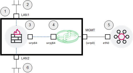
Legend Item
Description
1
ElasticXL Cluster in the VSNext mode.
2
Network #1 that sends traffic through the Virtual Gateway (3) to Network #2 (6).
3
Virtual Gateway that inspects traffic between Network #1 (2) and Network #2 (6).
Ports LAN1 and LAN2 are assigned to the Virtual Gateway.
4
Default Virtual Switch that connects the Virtual Gateway (3) to the Management Server (5).
-
The Virtual Gateway connects to the Virtual Switch over an internal virtual link from
wrp64towrpj64. -
"MGMT" is the name of the physical port on the Check Point appliance.
-
"wrp0" is the internal name of the "MGMT" port in the Gaia operating system.
5
Management Server that manages the Virtual Gateway (3) through its interface
wrp64.6
Network #2 that sends traffic through Virtual Gateway (3) to Network #1 (2).
Interfaces and IP addresses
Interface
IP Address / Net Mask
Description
eth0
192.168.3.57 / 24
Interface of the Management Server
wrp0
192.168.3.242 / 24
Management interface for the ElasticXL Cluster in the VSNext mode
wrp64
192.168.3.250 / 24
Management interface for the Virtual Gateway
LAN1
172.16.44.250 / 24
Interface of the Virtual Gateway that connects it to Network #1
LAN2
172.16.55.250 / 24
Interface of the Virtual Gateway that connects it to Network #2
Configuration:
-
From toolbar, click Add > Virtual Gateway.
-
In the section Network interfaces:
-
Click Add interface.
-
Select the checkboxes of the interfaces that you need to assign to this Virtual Gateway.
In our example, select LAN1 and LAN2.
-
Click Add.
-
-
In the section Establish trust with Management server:
-
In the Activation Key field, enter a one-time password.
You use this password later, when you create a Security Gateway object in SmartConsole.
-
In the Re-type Activation Key field, enter the one-time password again.
-
In the Interface field, select an interface, to which you need to assign an IPv4 address.
You use this IPv4 address later, when you create a Security Gateway object in SmartConsole.
In our example, select: mgmt-switch (500).
-
In the IPv4 address field, enter the required IPv4 address.
In our example, enter:
192.168.3.250 -
In the Mask length field, enter the required IPv4 mask length (from 1 to 32).
In our example, enter:
24 -
In the Default Gateway field, enter the required IPv4 address.
In our example, enter:
192.168.3.1 -
In the IPv6 address field, enter the required IPv6 address.
In our example, we do not use IPv6 addresses.
-
In the Mask length field, enter the required IPv6 mask length (from 1 to 128).
In our example, we do not use IPv6 addresses.
-
In the Default Gateway field, enter the required IPv4 address.
In our example, we do not use IPv6 addresses.
-
-
Optional: In the section Advanced settings:
-
On the right end of the section heading, click the arrow icon to expand this section.
-
In the Manually assigned VS ID field, enter the applicable ID between 1 and 511.
If you do not enter an ID, it is assigned automatically (the next available sequentical number).
-
In the Assign IPv4 Instances field, enter the applicable number of IPv4 CoreXL Firewall instances.
-
In the Assign IPv6 Instances field, enter the applicable number of IPv6 CoreXL Firewall instances.
-
-
Click OK.
The popup appears with next steps. Click OK.
We recommend to copy these steps and send them to yourself by email.
-
Monitor the progress in the bottom panel Tasks.
The Status column must show Completed.
For details, see these files on the ElasticXL Cluster / Maestro Security Group:
/var/log/vsxd.elg* -
On the top toolbar, in the field Virtual System, select the ID of the new Virtual Gateway.
-
In the left panel, click Network Management > Network Interfaces.
Configure the interfaces you assigned to the Virtual Gateway:
-
Select the interface LAN1 > click Edit > configure the IPv4 address 172.16.44.250 and IPv4 Subnet mask 255.255.255.0 > click OK.
-
Select the interface LAN2 > click Edit > configure the IPv4 address 172.16.55.250 and IPv4 Subnet mask 255.255.255.0 > click OK.
For more information, see the R82 Gaia Administration Guide > chapter "Network Management" > section "Network Interfaces" > section "Physical Interfaces".
-
-
In the left panel, click Network Management > IPv4 Static Routes.
Add the required static routes for this Virtual Gateway.
For more information, see the R82 Gaia Administration Guide > chapter "Network Management" > section "IPv4 Static Routes".
Configuration example - Two Virtual Gateways connect to a server through a Virtual Switch and are managed by different Management Servers
You can create many Virtual Gateways and manage each of them by different Security Management Servers / Domain Management Servers.
Each Virtual Gateway gets a unique IP address.
Example topology:
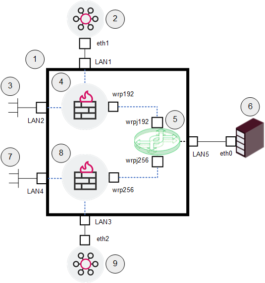
Legend Item
Description
1
ElasticXL Cluster in the VSNext mode.
2
Management Server #1 that manages the Virtual Gateway #1 (4) through its interface LAN1.
3
Network #1 that sends traffic through the Virtual Gateway #1 (4) to the Backup Server (6).
4
Virtual Gateway #1 that inspects traffic between Network #1 (3) and the Backup Server (6).
5
Virtual Switch that connects the Virtual Gateway #1 (4) and the Virtual Gateway #2 (8) through the interface LAN5 to the Server (6).
-
The Virtual Gateway #1 (4) connects over an internal virtual link from
wrp192towrpj192. -
The Virtual Gateway #2 (8) connects over an internal virtual link from
wrp256towrpj256.
6
Backup Server, to which Network #1 (3) and Network #2 (7) send their traffic.
7
Network #2 that sends traffic through the Virtual Gateway #2 (8) to the Backup Server (6).
8
Virtual Gateway #2 that inspects traffic between Network #2 (7) and the Backup Server (6).
9
Management Server #2 that manages the Virtual Gateway #2 (8) through its interface LAN3.
Interfaces and IP addresses
Interface
IP Address / Net Mask
Description
eth0
10.10.10.55 / 24
Interface of the Backup Server
eth1
192.168.3.57 / 24
Interface of the Management Server #1
eth2
192.168.5.57 / 24
Interface of the Management Server #2
LAN1
192.168.3.250 / 24
Interface of the Virtual Gateway #1 that connects it to the Management Server #1
LAN2
172.16.3.250 / 24
Interface of the Virtual Gateway #1 that connects it to Network #1
wrp192
None
Interface of the Virtual Gateway #1 that connects it to the Virtual Switch
LAN3
192.168.5.250 / 24
Interface of the Virtual Gateway #2 that connects it to the Management Server #2
LAN4
172.16.5.250 / 24
Interface of the Virtual Gateway #2 that connects it to Network #2
wrp256
None
Interface of the Virtual Gateway #2 that connects it to the Virtual Switch
Configuration Part 1 - Configure Virtual Switch:
-
From toolbar, click Add > Virtual Switch.
-
In the Name field, enter a name for this object.
It must start with a letter, and may contains only letters, digits, dash, and underscore.
In our example, enter:
ServerSwitch -
In the Interface field, select an interface, to which this Virtual Switch connects.
In our example, select LAN5.
-
Click Apply.
Configuration Part 2 - Configure Virtual Gateway #1:
-
On the top toolbar, after the field Virtual System, if you see the padlock icon, then click the padlock icon, and click Yes to override the lock.
The padlock icon must change to the pencil icon.
-
From toolbar, click Add > Virtual Gateway.
-
In the section Network interfaces:
-
Select the default interface New connection to "mgmt-switch (500)" and click Remove.
-
Click Connect to Switch > select the Virtual Switch called "
ServerSwitch" > click Add. -
Click Add interface.
-
Select the checkboxes of the interfaces that you need to assign to this Virtual Gateway > click Add.
In our example, select LAN1 and LAN2.
-
-
In the section Establish trust with Management server:
-
In the Activation Key field, enter a one-time password.
You use this password later, when you create a Security Gateway object in SmartConsole.
-
In the Re-type Activation Key field, enter the one-time password again.
-
In the Interface field, select an interface, to which you need to assign an IPv4 address.
You use this IPv4 address later, when you create a Security Gateway object in SmartConsole.
In our example, select: LAN1.
-
In the IPv4 address field, enter the required IPv4 address.
In our example, enter:
192.168.3.250 -
In the Mask length field, enter the required IPv4 mask length (from 1 to 32).
In our example, enter:
24 -
In the Default Gateway field, enter the required IPv4 address.
In our example, enter:
192.168.3.1 -
In the IPv6 address field, enter the required IPv6 address.
In our example, we do not use IPv6 addresses.
-
In the Mask length field, enter the required IPv6 mask length (from 1 to 128).
In our example, we do not use IPv6 addresses.
-
In the Default Gateway field, enter the required IPv6 address.
In our example, we do not use IPv6 addresses.
-
-
Optional: In the section Advanced settings:
-
On the right end of the section heading, click the arrow icon to expand this section.
-
In the Manually assigned VS ID field, enter the applicable ID between 1 and 511.
If you do not enter an ID, it is assigned automatically (the next available sequentical number).
-
In the Assign IPv4 Instances field, enter the applicable number of IPv4 CoreXL Firewall instances.
-
In the Assign IPv6 Instances field, enter the applicable number of IPv6 CoreXL Firewall instances.
-
-
Click OK.
The popup appears with next steps. Click OK.
We recommend to copy these steps and send them to yourself by email.
-
Monitor the progress in the bottom panel Tasks.
The Status column must show Completed.
For details, see these files on the ElasticXL Cluster / Maestro Security Group:
/var/log/vsxd.elg* -
On the top toolbar, in the field Virtual System, select the ID of the new Virtual Gateway.
-
In the left panel, click Network Management > Network Interfaces.
Configure the interfaces you assigned to the Virtual Gateway:
-
The interface LAN1 already has the IPv4 address 192.168.3.250 and IPv4 Subnet mask 255.255.255.0.
-
Select the interface LAN2 > click Edit > configure the IPv4 address 172.16.3.250 and IPv4 Subnet mask 255.255.255.0 > click OK.
For more information, see the R82 Gaia Administration Guide > chapter "Network Management" > section "Network Interfaces" > section "Physical Interfaces".
-
-
In the left panel, click Network Management > IPv4 Static Routes.
Add the required static routes for this Virtual Gateway.
For more information, see the R82 Gaia Administration Guide > chapter "Network Management" > section "IPv4 Static Routes".
Configuration Part 3 - Configure Virtual Gateway #2:
-
On the top toolbar, after the field Virtual System, if you see the padlock icon, then click the padlock icon, and click Yes to override the lock.
The padlock icon must change to the pencil icon.
-
From toolbar, click Add > Virtual Gateway.
-
In the section Network interfaces:
-
Select the default interface New connection to "mgmt-switch (500)" and click Remove.
-
Click Connect to Switch > select the Virtual Switch called "
ServerSwitch" > click Add. -
Click Add interface.
-
Select the checkboxes of the interfaces that you need to assign to this Virtual Gateway > click Add.
In our example, select LAN3 and LAN4.
-
-
In the section Establish trust with Management server:
-
In the Activation Key field, enter a one-time password.
You use this password later, when you create a Security Gateway object in SmartConsole.
-
In the Re-type Activation Key field, enter the one-time password again.
-
In the Interface field, select an interface, to which you need to assign an IPv4 address.
You use this IPv4 address later, when you create a Security Gateway object in SmartConsole.
In our example, select: LAN3.
-
In the IPv4 address field, enter the required IPv4 address.
In our example, enter:
192.168.5.250 -
In the Mask length field, enter the required IPv4 mask length (from 1 to 32).
In our example, enter:
24 -
In the Default Gateway field, enter the required IPv4 address.
In our example, enter:
192.168.5.1 -
In the IPv6 address field, enter the required IPv6 address.
In our example, we do not use IPv6 addresses.
-
In the Mask length field, enter the required IPv6 mask length (from 1 to 128).
In our example, we do not use IPv6 addresses.
-
In the Default Gateway field, enter the required IPv6 address.
In our example, we do not use IPv6 addresses.
-
-
Optional: In the section Advanced settings:
-
On the right end of the section heading, click the arrow icon to expand this section.
-
In the Manually assigned VS ID field, enter the applicable ID between 1 and 511.
If you do not enter an ID, it is assigned automatically (the next available sequentical number).
-
In the Assign IPv4 Instances field, enter the applicable number of IPv4 CoreXL Firewall instances.
-
In the Assign IPv6 Instances field, enter the applicable number of IPv6 CoreXL Firewall instances.
-
-
Click OK.
The popup appears with next steps. Click OK.
We recommend to copy these steps and send them to yourself by email.
-
Monitor the progress in the bottom panel Tasks.
The Status column must show Completed.
For details, see these files on the ElasticXL Cluster / Maestro Security Group:
/var/log/vsxd.elg* -
On the top toolbar, in the field Virtual System, select the ID of the new Virtual Gateway.
-
In the left panel, click Network Management > Network Interfaces.
Configure the interfaces you assigned to the Virtual Gateway:
-
The interface LAN3 already has the IPv4 address 192.168.5.250 and IPv4 Subnet mask 255.255.255.0.
-
Select the interface LAN4 > click Edit > configure the IPv4 address 172.16.5.250 and IPv4 Subnet mask 255.255.255.0 > click OK.
For more information, see the R82 Gaia Administration Guide > chapter "Network Management" > section "Network Interfaces" > section "Physical Interfaces".
-
-
In the left panel, click Network Management > IPv4 Static Routes.
Add the required static routes for this Virtual Gateway.
For more information, see the R82 Gaia Administration Guide > chapter "Network Management" > section "IPv4 Static Routes".

Note - You can assign additional interfaces to a Virtual Gateway later.
-
On the top toolbar, in the field Virtual System, select the default Virtual Gateway with ID 0.
-
In the left panel, click the Virtual Systems page.
-
Click the Virtual Gateway object.
-
From the top toolbar, click Edit.
-
-
On the ElasticXL Cluster / Maestro Security Group, in the context of each Virtual Gateway, configure additional applicable Gaia OS settings - Interfaces, DNS, Hosts, Static Routes, and Dynamic Routing.
See the:
Each Virtual Gateway behaves as a regular Security Gateway.
Configuration in Gaia Portal
-
Connect to Gaia Portal on the ElasticXL Cluster / Maestro Security Group.
-
On the top toolbar, in the field Virtual System, select the required Virtual Gateway.
-
Configure the additional applicable Gaia OS settings.
Configuration in Gaia gClish
-
Connect to the command line on the ElasticXL Cluster / Maestro Security Group.
-
Log in.
-
If your default shell is the Expert mode, then go to Gaia gClish:
gclish -
Go to the context of the required Virtual Gateway:
set virtual-system <ID> -
Configure the additional applicable Gaia OS settings.
-
-
In SmartConsole, configure the Security Gateway object for each Virtual Gateway.
Configuration
Best Practice - Configure a Security Gateway object for the default Virtual Gateway (with ID 0) to ensure secure access through the "MGMT" port.
The default Virtual Gateway is intended only for the management traffic.
-
Connect with SmartConsole to the Security Management Server / Domain Management Server that needs to manage the applicable Virtual Gateway.
-
From the left navigation panel, click Gateways & Servers.
-
Create a new Security Gateway object for each Virtual Gateway:
From the top toolbar, click New (
 ) > Gateway:
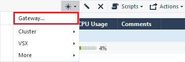 Additional Available Options
-
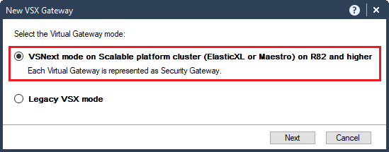
From the top toolbar, click New (
) > VSX > Gateway: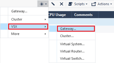
and in the New VSX Gateway window:
-
Select VSNext mode on Scalable platform cluster (ElasticXL or Maestro) on R82 and higher.
-
Click Next.
-
-
In the top right corner, click the Objects panel > click New (
) > More > Network Object > Gateways and Servers > Gateway. -
In the top right corner, click the Objects panel > click New (
) > More > Network Object > Gateways and Servers > VSX > Gateway > and in the New VSX Gateway window:-
Select VSNext mode on Scalable platform cluster (ElasticXL or Maestro) on R82 and higher.
-
Click Next.
-
-
-
In the Name field, enter a desired name.
Note - After the first policy installation, the name you assign to the Security Gateway object in SmartConsole appears in Gaia Portal of the ElasticXL Cluster / Maestro Security Group:
-
On the top toolbar, in the field Virtual System.
-
On the page Virtual Systems in the column Name.
-
-
In the IPv4 Address field, enter the same IPv4 address you configured for this Virtual Gateway in Gaia Portal / Gaia gClish of the ElasticXL Cluster / Maestro Security Group.
-
In the IPv6 Address field, enter the same IPv6 address you configured for this Virtual Gateway in Gaia Portal / Gaia gClish of the ElasticXL Cluster / Maestro Security Group.
-
Establish the Secure Internal Communication:
-
Near the Secure Internal Communication field, click Communication.
-
In the Platform field, select Open server / Appliance.
-
Enter the same Activation Key you configured for this Virtual Gateway in Gaia Portal / Gaia gClish of the ElasticXL Cluster / Maestro Security Group.
-
Click Initialize.
The Certificate state field must show "
Established". -
Click OK to close the Trusted Communication window.
-
-
Make sure the Security Gateway object shows the correct values:
-
The Hardware field must show:
-
For an ElasticXL Cluster, must show ElasticXL.
-
For a Maestro Security Group, must show Maestro.
-
-
The Version field must show R82.
-
The OS field must show Gaia.
-
The Virtualization field must show VS.
-
-
Enable and configure the required Software Blades.
Refer to the corresponding Administration Guide on the R82 Home Page.
- Click OK to close the Check Point Gateway window.
-
Publish the SmartConsole session.
-
-
In SmartConsole, configure and install the applicable Security Policies for each Virtual Gateway.
Configuration
Best Practice - Configure and install a Security Policy for the default Virtual Gateway (with ID 0) to ensure secure access.
Allow administration access to the ElasticXL Cluster / MaestroSecurity Group and to each Virtual Gateway only from secured hosts and networks.
The administration access requires HTTPS (for Gaia Portal) and SSH (for command line). Optionally, allow ICMP (for pings).
-
Configure the applicable Access Control policy for each Virtual Gateway.
-
Configure the applicable Threat Prevention policy for each Virtual Gateway.
-
Install the Access Control policy and the Threat Prevention policy on each Virtual Gateway.
-
-
Add the additional required appliances to this ElasticXL Cluster / Maestro Security Group.
The new Security Group Members automatically copy the required settings.
See the R82 Scalable Platforms Administration Guide:
-
For an ElasticXL Cluster:
Chapter "Working with ElasticXL Cluster".
-
For a Maestro Security Group.
Chapter "Working with Quantum Maestro".
-