Deploying VSX - Internal Network Deployment Strategies
Security Gateway Deployment on a Physical Network
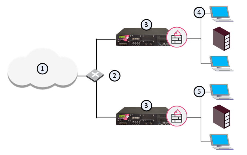
In large physical network deployments, multiple Check Point security products, such as Security Gateways, are deployed to protect network segments.
|
Item |
Description |
|---|---|
|
1 |
Internet |
|
2 |
Router |
|
3 |
Security Gateways |
|
4 |
Network 1 |
|
5 |
Network 2 |
Each Security Gateway physically connects to its own internal protected network and to a router for access to other internal networks and the Internet.
VSX Virtual System Deployment Strategies
In a VSX environment, Virtual Systems protect internal networks.
This section shows sample VSX deployments with Virtual Systems to protect internal networks.
Each example highlights different VSX features.
In a real-world deployment, you can combine features to create a powerful cyber security solution for complex enterprise environments.
Physical Internal Interface for Each Virtual System
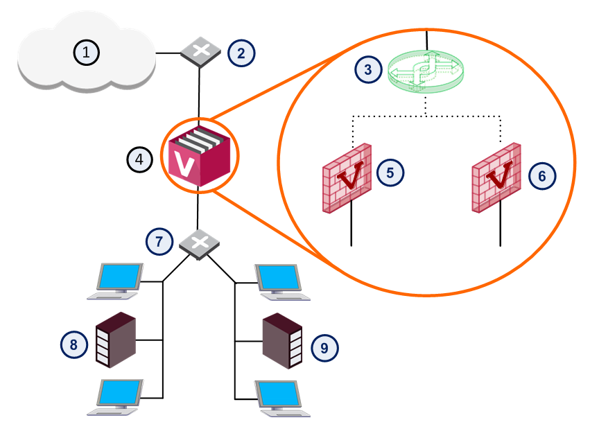
In a basic VSX configuration, Virtual Systems connect directly to protected internal networks through physical interfaces on the VSX Gateway.
A Virtual Switch connects between internal networks, and to the Internet.
This deployment is suitable for protecting a small, fixed quantity of internal networks.
The main disadvantage of this deployment is that each protected network requires its own dedicated physical interface on the VSX Gateway.
Obviously, this deployment is not suitable for networks that require many Virtual Systems.
|
Item |
Description |
|
Item |
Description |
|---|---|---|---|---|
|
1 |
Internet |
|
6 |
Virtual System 2 |
|
2 |
Router |
|
7 |
Switch |
|
3 |
Virtual Switch |
|
8 |
Network 1 |
|
4 |
VSX Gateway |
|
9 |
Network 2 |
|
5 |
Virtual System 1 |
|
|
Warp Link |

Virtual Systems with Internal VLAN Interfaces
In this deployment example, Virtual Systems connect to internal protected networks through VLAN interfaces.
The VSX Gateway connects to a VLAN switch with an 802.1q VLAN trunk, which is an aggregate of all VLANs passing through it.
This deployment option is appropriate for environments where many Virtual Systems protect many internal networks with one VSX Gateway or cluster.
VLANs provide scalability and granularity, to provision more Virtual Systems and protected networks quickly, without changing the existing IP address structure.

Internal Virtual Router with Source-Based Routing
|
|
Note - Security Groups in Maestro and Scalable Chassis do not support Virtual Routers (Known Limitation 01413513). |

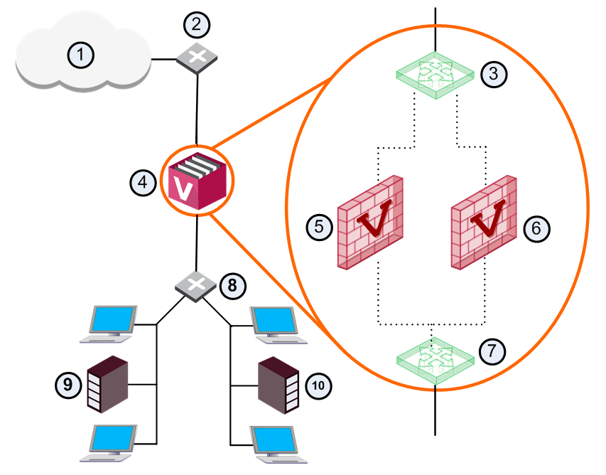
This deployment scenario enables Virtual Systems to connect to protected networks using a single physical interface without VLAN technology.
The Virtual Router uses source-based routing rules to forward traffic to the appropriate Virtual System based on its source IP address.
In a VSX deployment with each Virtual System connected to a single Virtual Router: You can configure the Virtual Router to use source-based routing rules, to forward traffic to the appropriate Virtual System, based on the source IP address.
|
Item |
Description |
|
Item |
Description |
|---|---|---|---|---|
|
1 |
Internet |
|
7 |
Virtual Router |
|
2 |
Router |
|
8 |
Router |
|
3 |
Virtual Switch |
|
9 |
Network 1 |
|
4 |
VSX Gateway |
|
10 |
Network 2 |
|
5 |
VS 1 |
|
|
Warp link |
|
6 |
VS 2 |
|
|
|
Notes for this scenario:
-
Each Virtual System uses a public IP address to connect to the Virtual Switch.
-
Each local network connected to a Virtual Router uses private IP addresses.
-
This deployment does not support overlapping IP addresses.
-
Anti-Spoofing protection does function for packets originating from the shared internal interface.
We recommend that you configure the internal physical router to perform Anti-Spoofing protection.
Virtual Systems in Bridge Mode
A Virtual System in bridge mode implements native Layer 2 bridging instead of IP routing and can co-exist with Layer 3 Virtual Systems on the same VSX Gateway.
This allows network administrators to easily and transparently deploy a Virtual System in an existing network topology without reconfiguring the existing IP routing scheme.
Bridge Mode deployments are particularly suitable for large-scale clustered environments.
See Bridge Mode.