Route-Based VPN
Overview of Route-Based VPN
Route-Based VPN![]() A routing method for participants in a VPN community, defined by network routes. provides a flexible and scalable approach to secure communication between Security Gateways. Unlike traditional domain-based VPNs, Route-Based VPN leverages virtual interfaces - known as VPN Tunnel
A routing method for participants in a VPN community, defined by network routes. provides a flexible and scalable approach to secure communication between Security Gateways. Unlike traditional domain-based VPNs, Route-Based VPN leverages virtual interfaces - known as VPN Tunnel![]() An encrypted connection between two hosts using standard protocols (such as L2TP) to encrypt traffic going in and decrypt it coming out, creating an encapsulated network through which data can be safely shared as though on a physical private line. Interfaces (VTIs) - to route traffic dynamically based on IP routing decisions.
An encrypted connection between two hosts using standard protocols (such as L2TP) to encrypt traffic going in and decrypt it coming out, creating an encapsulated network through which data can be safely shared as though on a physical private line. Interfaces (VTIs) - to route traffic dynamically based on IP routing decisions.
Each VTI acts as a virtual point-to-point link between peer Security Gateways, enabling encrypted traffic to flow seamlessly across the VPN tunnel, that are defined with all of its properties within a VPN Community![]() A named collection of VPN domains, each protected by a VPN gateway..
A named collection of VPN domains, each protected by a VPN gateway..
Traffic destined for a peer's VPN domain is automatically routed through the corresponding VTI, allowing the use of dynamic routing protocols such as OSPF or BGP. This setup enables routing daemons on each gateway to exchange information as if they were directly connected, improving network adaptability and performance.
Route-Based VPN can only be implemented between Security Gateways within the same VPN Community.
Simplified Route-Based VPN
Simplified Route-Based VPN Overview
Starting from R82.10, you can use Simplified Route-Based VPN to automate the configuration of Route-Based VPNs, including Virtual Tunnel Interfaces (VTIs) and dynamic routing protocols such as BGP. It makes manual setup easier, improves consistency, and accelerates deployment across Check Point environments.
Simplified Route-Based VPN supports both Mesh and Star (hub-and-spoke) VPN communities and is fully integrated with SmartConsole![]() Check Point GUI application used to manage a Check Point environment - configure Security Policies, configure devices, monitor products and events, install updates, and so on..
Check Point GUI application used to manage a Check Point environment - configure Security Policies, configure devices, monitor products and events, install updates, and so on..
Simplified Route-Based VPN Key Features
-
Unified Configuration: All the setup is done within SmartConsole. There is no need to manually configure each Security Gateway
 Dedicated Check Point server that runs Check Point software to inspect traffic and enforce Security Policies for connected network resources. separately.
 -
Auto-Generated VTIs: VTIs with editable IP addresses are created automatically between internally managed Security Gateways in the VPN community..
-
Auto-Generated Dynamic Routing: BGP settings are created automatically on the Security Gateways based on the VPN community and Security Gateway configuration in the Management Server
Check Point Single-Domain Security Management Server or a Multi-Domain Security Management Server.. -
Simplified Policy Matching: Select the VPN community object in the VPN column of the Access Control policy rule
Set of traffic parameters and other conditions in a Rule Base (Security Policy) that cause specified actions to be taken for a communication session. to match the Route-Based VPN traffic. -
Better performance: Host-to-host tunnel is supported when all members in the Route-Based VPN community are R82.10Check PointSecurity Gateways, enabling better tunnel distribution on the Gateway's cores.
-
Manual Overrides: Administrators can override VTI IP addresses, ASN, and BGP settings.
-
Topology Support: Compatible with on-premises and cloud architectures.
-
Interoperability: Supports clusters, VSX
Virtual System Extension. Check Point virtual networking solution, hosted on a computer or cluster with virtual abstractions of Check Point Security Gateways and other network devices. These Virtual Devices provide the same functionality as their physical counterparts., and third-party devices with manual configuration on remote peers. -
Automatic Cleanup: When gateways are deleted or route-based VPN is disabled, configuration is automatically removed.

Note - Manual VTI and BGP configuration are not removed automatically.
-
Handle conflicts: Detects and preserves manual configurations: Identifies existing Route-Based configurations, such as VTIs and BGP settings, and does not change them.
Simplified Route-Based VPN Limitations
-
OSPF and iBGP are not supported.
-
CGNAT devices and Check Point host objects are not supported.
-
GVC, unnumbered VTIs, and VPN Profiles (for example, LSM and LSV) are not supported.
-
Quantum Spark appliances are not supported.
-
VSNext is not supported.
-
On VSX (Legacy) Gateways, you must manually delete the VTIs if you discard the Route-Based configuration before completion.
-
Database Revisions are not supported, as the Route-Based configuration is transferred to the Security Gateways separately from the policy package.
Simplified Route-Based VPN Configuration
To configure Simplified Route-Based VPN:
-
Enable Route-Based VPN:
-
In SmartConsole, open the Objects Pane (F11).
-
Click VPN Communities, and open the applicable community.
-
In the Gateways tab > Routing Mode section, select Route-Based.
-
-
Configure the community general BGP settings:
-
To configure the Route-Based settings, click the Edit button next to Route-Based.
-
In BGP Settings, the apply BGP configuration check-box is selected by default. Clear this option if you do not want to automatically create a BGP configuration on your Security Gateways.
-
In the Advanced settings, select if you want to use Bidirectional Forwarding Detection (BFD) and if you want to support Graceful Restart.
-
To save the Route-Based Settings, click OK.
-
-
You can configure the specific BGP settings for a Security Gateway in this VPN community, or you can configure the Security Gateway’s BGP settings in the Gateway’s object properties later.
To configure the specific BGP settings for a Security Gateway in this VPN community:
-
Double-click the Security Gateway name in the Gateways section. The VPN configuration for the Security Gateway in this VPN community window opens.
-
BGP Settings: Select one of these options to apply the BGP configuration:
-
Based on the Security Gateway object configuration.
-
Override: Select which routes to export:
-
Export interfaces with Topology 'Internal' - Match protocol direct.
-
Export local static routes - Match protocol static.
-
Export custom routes - Match protocols direct, static, and BGP.
-
-
-
To save the VPN configuration settings for this Security Gateway, click OK.
-
-
To save the changes in the VPN community, click OK.
Note - The VPN Configuration Engine (VCE) automatically creates VTIs and allocates Autonomous System Number (ASN) values as needed.
These changes are displayed as a prepare task in the task viewer.
-
Customize Settings (Optional).
You can override the automatic VTI, ASN, or the BGP settings for a Security Gateway or VPN community.
-
To change the VTI IP address:
-
In the SmartConsole, click Gateways & Servers.
-
Double-click the applicable Security Gateway object to open its properties page.
-
Open Network Management.
-
Select the applicable VTI interface (starting with vpnt) and open it.
-
On the General tab, configure the interface IP address.
-
On the VPN Tunnel tab, configure the Peer Gateway IP address.
-
Click OK to save the settings.
-
-
To override the Gateway’s default community settings in a specific VPN community:
-
In SmartConsole, click Gateways & Servers.
-
Double-click the applicable Security Gateway object to open its properties page.
-
Go to IPSec VPN > Route-Based VPN.
-
In the Exported Routes section, select which routes to export:
-
Interfaces with Topology internal.
-
Local static routes.
-
Custom routes - Select a network or a network group from the list or create a new group.
-
-
-
ASN Configuration:
-
For Externally Managed Gateways and Interoperable Devices:
-
In SmartConsole, open Object Explorer (F11).
-
Find the applicable Externally Managed Gateway/Interoperable Device and click to open the object properties.
-
Go to IPSec VPN > Route-Based VPN.
-
In the BGP Autonomous System page, enter the Local ASN.
-
-
For Internally Managed Security Gateways:
Configure the ASN in WebUI or in Clish. For details, refer to R82.10 Gaia Advanced Routing Administration Guide.
Note - The ASN number is fetched automatically from Check Point Internally Managed Security Gateways.
-
-
-
Add rules in the Access Control policy
Starting in R82.10, Route-Based VPN traffic can be matched directly by selecting the community object in the VPN column of the Access Control policy rule. There is no need to configure VPN directional rules for accepting Route-Based VPN traffic.
Note - When both community-based and directional VPN rules exist for the same community, the community-based rule takes precedence for matching Route-Based VPN traffic.
-
Publish the changes in SmartConsole and install the policy.
After the policy installation, the VCE pushes the configuration to the Security Gateways.
Note - SmartConsole shows an Applying the VPN Route-Based Settings on Policy Targets task with the changes.
-
Verification:
Examine the Security Gateway configuration for auto-generated VTIs and BGP settings. These are marked with an auto-generated comment in the Gaia
Check Point security operating system that combines the strengths of both SecurePlatform and IPSO operating systems. configuration.
|
|
Important -Disabling Route-Based VPN or removing gateways from the community removes the related automatic configuration. |
Troubleshooting
Log files:
-
VCE logs are available for auditing and troubleshooting. They are located in the $FWDIR/log/VCE/* directory.
-
Management Server logs are in $FWDIR/log/CPM.elg.
Manual Route-Based VPN
Manual Route-Based VPN is the former method of using this feature, and is still supported in R82.10.
VPN Tunnel Interface (VTI)
A VTI is the foundational component of a Route-Based VPN. It acts as a virtual point-to-point interface on a Security Gateway, enabling encrypted communication with a remote peer. Each VTI corresponds to a specific VPN tunnel and is configured on both ends of the connection. Once established, traffic routed through the VTI is automatically encrypted and securely delivered to the peer Security Gateway.
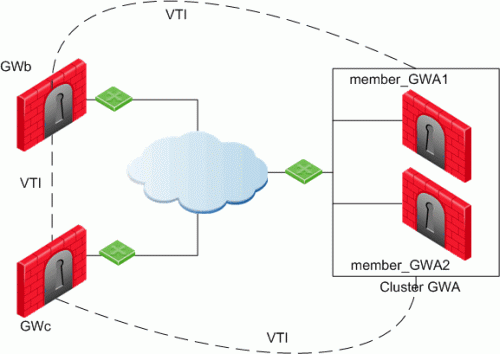
In this scenario:
-
There is a VTI connecting "Cluster
Two or more Security Gateways that work together in a redundant configuration - High Availability, or Load Sharing. GWa" and "GWb" (you must configure the same Tunnel ID on these peers) -
There is a VTI connecting "Cluster GWa" and "GWc" (you must configure the same Tunnel ID on these peers)
-
There is a VTI connecting "GWb" and "GWc" (you must configure the same Tunnel ID on these peers)
A virtual interface behaves like a point-to-point interface directly connected to the remote peer. Traffic between network hosts is routed into the VPN tunnel with the IP routing mechanism of the Operating System. Security Gateway objects are still required, as well as VPN Communities (and Access Control policies) to define which tunnels are available. However, VPN Encryption Domains for each peer Security Gateway are no longer necessary. The decision whether or not to encrypt depends on whether the traffic is routed through a virtual interface. The routing changes dynamically if a dynamic routing protocol (OSPF/BGP) is available on the network.
When a connection that originates on GWb is routed through a VTI to GWc (or servers behind GWc) and is accepted by the implied rules, the connection leaves GWb in the clear with the local IP address of the VTI as the source IP address. If this IP address is not routable, return packets will be lost.
The possible solutions for this issue are:
-
Configure a static route on GWb that redirects packets destined to GWc from being routed through the VTI
-
Not including it in any published route
-
Adding route maps that filter out GWc's IP addresses
Having excluded those IP addresses from route-based VPN, it is still possible to have other connections encrypted to those addresses (i.e. when not passing on implied rules) by using Domain-based VPN definitions.
The VTI can be configured in two ways:
|
VTI Type |
Description |
|---|---|
|
Numbered |
You configure a local and remote IP address for each numbered VPN Tunnel Interface (VTI). For each Security Gateway, you configure a local IP address, a remote address, and the local IP address source for outbound connections to the tunnel. The remote IP address must be the local IP address on the remote peer Security Gateway. More than one VTI can use the same IP Address, but they cannot use an existing physical interface IP address. |
|
Unnumbered |
For unnumbered VTIs, you define a proxy interface for each Security Gateway. Each Security Gateway uses the proxy interface IP address as the source for outbound traffic. Unnumbered interfaces let you assign and manage one IP address for each interface. Proxy interfaces can be physical or loopback interfaces. |
Using Dynamic Routing Protocols
VTIs allow the ability to use Dynamic Routing Protocols to exchange routing information between Security Gateways.
The Dynamic Routing Protocols supported on Gaia are:
-
BGP4
-
OSPFv2
-
RIPv1
-
RIPv2
VTIs in a Clustered Environment
When configuring numbered VTIs in a clustered environment, a number of issues need to be considered:
-
Each member must have a unique source IP address.
-
Every interface on each member requires a unique IP address.
-
All VTIs going to the same remote peer must have the same name.
-
Cluster IP addresses are required.
Configuring VTIs in Gaia Operating System
See the R82.10 Gaia Administration Guide > Chapter Network Management > Section Network Interfaces > Section VPN Tunnel Interfaces.
Note - For VTIs between Gaia Security Gateways and Cisco GRE gateways, you must manually configure the Hello/Dead packet intervals at 10/40 on the Gaia Security Gateways, or at 30/120 on the peer gateway. If not, OSPF is not able to get into the "FULL" state.
Enabling Route-Based VPN
If you configure a Security Gateway for Domain-Based VPN and Route-Based VPN, then Domain-Based VPN takes precedence by default.
To force Route-Based VPN to take priority, you must create an empty group object and assign it to the VPN domain.
To force Route-Based VPN to take priority:
-
In SmartConsole, from the left navigation panel, click Gateways & Servers.
-
Open the Security Gateway / Cluster object.
-
From the left tree, click Network Management > VPN Domain.
-
Select User defined.
-
Click the [...] button.
-
Click New > Group > Simple Group.
-
Enter a Name.
-
Click OK (leave this Group object empty).
Configuring Numbered VTIs - Example
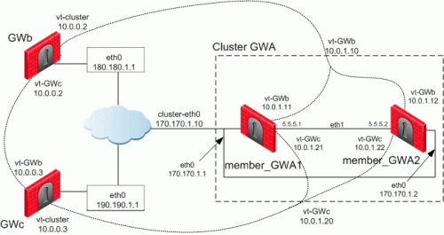
The Security Gateways in this scenario are:
|
Device Type |
Specific Computers |
|---|---|
|
ClusterXL |
Cluster GWa:
|
|
VPN peers |
|
VTIs connect these Security Gateways:
-
Members of "
Cluster GWa" and "GWb" -
Members of "
Cluster GWa" and "GWc" -
"
GWb" and "GWc"
IP Configuration:
|
Peer |
Type of IP Address and Interface |
IP Address / Netmask |
|---|---|---|
|
Cluster GWa |
External Unique IP address of |
170.170.1.1 / 24 |
|
member_GWa1 |
External VIP address of |
170.170.1.10 / 24 |
|
|
IP address of Sync interface |
5.5.5.1 / 24 |
|
|
IP address of VTI for " |
Local: 169.254.1.11 / 32 Remote: 169.254.0.2 / 32 |
|
|
VIP address of VTI for " |
169.254.1.10 / 32 |
|
|
IP address of VTI for " |
Local: 169.254.1.21 / 32 Remote: 169.254.0.3 / 32 |
|
|
VIP address of VTI for " |
169.254.1.20 / 32 |
|
Cluster GWa |
External Unique IP address of |
170.170.1.2 / 24 |
|
member_GWa2 |
External VIP address of |
170.170.1.10 / 24 |
|
|
IP address of Sync interface |
5.5.5.2 / 24 |
|
|
IP address of VTI for " |
Local: 169.254.1.12 / 32 Remote: 169.254.0.2 / 32 |
|
|
VIP address of VTI for " |
169.254.1.10 / 32 |
|
|
IP address of VTI " |
Local: 169.254.1.22 / 32 Remote: 169.254.0.3 / 32 |
|
|
VIP address of VTI for " |
169.254.1.20 / 32 |
|
GWb |
External Unique IP address of |
180.180.1.1 / 24 |
|
|
IP address of VTI for " |
Local: 169.254.0.2 / 32 Remote: 169.254.1.10 / 32 |
|
|
IP address of VTI " |
Local: 169.254.0.5 / 32 Remote: 169.254.0.3 / 32 |
|
GWc |
External Unique IP address of |
190.190.1.1 / 24 |
|
|
IP address of VTI for " |
Local: 169.254.0.3 / 32 Remote: 169.254.1.20 / 32 |
|
|
IP address of VTI for " |
Local: 169.254.0.4 / 32 Remote: 169.254.0.2 / 32 |
The example configurations below use the same Security Gateway names and IP addresses that are described in Numbered VTIs.
-
Configure the required VTIs on 'member_GWa1'
See the R82.10 Gaia Administration Guide > Chapter Network Management > Section Network Interfaces > Section VPN Tunnel Interfaces.
-
Configure a Numbered VPN Tunnel Interface for GWb.
Use these settings for the VTI:
Parameter
Value
VPN Tunnel ID
Integer from 1 to 9999

Important - You must configure the same ID for GWb on all Cluster Members.
Peer
GWb
VPN Tunnel Type
Numbered
Local Address
10.0.1.11
Remote Address
10.0.0.2
-
Configure a Numbered VPN Tunnel Interface for GWc.
Use these settings for the VTI:
Parameter
Value
VPN Tunnel ID
Integer from 1 to 9999
Important - You must configure the same ID for GWc on all Cluster Members.
Peer
GWc
VPN Tunnel Type
Numbered
Local Address
10.0.1.21
Remote Address
10.0.0.3
-
-
Configure the required VTIs on 'member_GWa2'
See the R82.10 Gaia Administration Guide > Chapter Network Management > Section Network Interfaces > Section VPN Tunnel Interfaces.
-
Configure a Numbered VPN Tunnel Interface for GWb.
Use these settings for the VTI:
Parameter
Value
VPN Tunnel ID
Integer from 1 to 9999
Important - You must configure the same ID for GWb on all Cluster Members.
Peer
GWb
VPN Tunnel Type
Numbered
Local Address
10.0.1.12
Remote Address
10.0.0.2
-
Configure a Numbered VPN Tunnel Interface for GWc.
Use these settings for the VTI:
Parameter
Value
VPN Tunnel ID
Integer from 1 to 9999
Important - You must configure the same ID for GWc on all Cluster Members.
Peer
GWc
VPN Tunnel Type
Numbered
Local Address
10.0.1.22
Remote Address
10.0.0.3
-
-
Configure the required VTIs on 'GWb'
See the R82.10 Gaia Administration Guide > Chapter Network Management > Section Network Interfaces > Section VPN Tunnel Interfaces.
-
Configure a Numbered VPN Tunnel Interface for Cluster GWa.
Use these settings for the VTI:
Parameter
Value
VPN Tunnel ID
Integer from 1 to 9999
Important - You must configure the same ID you configured on all Cluster Members for GWb.
Peer
ClusterGWa
VPN Tunnel Type
Numbered
Local Address
10.0.0.2
Remote Address
10.0.1.10
-
Configure a Numbered VPN Tunnel Interface for GWc.
Use these settings for the VTI:
Parameter
Value
VPN Tunnel ID
Integer from 1 to 9999
Important - You must configure the same ID for this VTI on GWb and GWc.
Peer
GWc
VPN Tunnel Type
Numbered
Local Address
10.0.0.2
Remote Address
10.0.0.3
-
-
Configure the required VTIs on 'GWc'
See the R82.10 Gaia Administration Guide > Chapter Network Management > Section Network Interfaces > Section VPN Tunnel Interfaces.
-
Configure a Numbered VPN Tunnel Interface for Cluster GWa.
Use these settings for the VTI:
Parameter
Value
VPN Tunnel ID
Integer from 1 to 9999
Important - You must configure the same ID you configured on all Cluster Members for GWc.
Peer
ClusterGWa
VPN Tunnel Type
Numbered
Local Address
10.0.0.3
Remote Address
10.0.1.20
-
Configure a Numbered VPN Tunnel Interface for GWb.
Use these settings for the VTI:
Parameter
Value
VPN Tunnel ID
Integer from 1 to 9999
Important - You must configure the same ID for this VTI on GWc and GWb.
Peer
GWb
VPN Tunnel Type
Numbered
Local Address
10.0.0.3
Remote Address
10.0.0.2
-
-
Configure the Cluster object in SmartConsole
After configuring the VTIs on the cluster members, you must configure the Cluster Virtual IP addresses of these VTIs in the cluster object in SmartConsole.
-
From the left navigation panel, click Gateways & Servers.
-
Right-click the cluster object and select Edit.
-
From the left tree, click Network Management.
-
Click Get Interfaces > Get Interfaces Without Topology.
The VTIs appear in the Topology column as Point to point.
Interfaces are members of the same VTI if these criteria match:
-
Peer
-
Remote IP address
-
Interface name
-
-
Configure the Cluster Virtual IP addresses on the VTIs:
-
Select the VTI interface and click Edit.
-
On the General page, enter the Virtual IP address.
-
Click OK.
Virtual IP Addresses:
Name
Topology
Virtual IP
member_GWa1
member_GWa2
Comment
vpnt1
Point to point
10.0.1.10
10.0.1.11
10.0.1.12
VTI with GWb
vpnt2
Point to point
10.0.1.20
10.0.1.21
10.0.1.22
VTI with GWc
-
-
Click OK.
-
Install the Access Control Policy on the cluster object.
-
Enabling Dynamic Routing Protocols on VTIs - Example
The example below shows how the OSPF dynamic routing protocol is enabled on VTIs.
Note that the network commands for single members and cluster members are not the same.
For more information on VTIs and advanced routing commands, see the:
When peering with a Cisco GRE enabled device, a point to point GRE tunnel is required.
Configuration:
vpnt1 is the VTI between 'member_GWa1' and 'GWb'
vpnt2 is the VTI between 'member_GWa1' and 'GWc'
member_GWa1:0> set ospf area 0.0.0.0 on member_GWa1:0> set router-id 170.170.1.10 member_GWa1:0> set ospf interface vpnt1 area 0.0.0.0 on member_GWa1:0> set ospf interface vpnt2 area 0.0.0.0 on member_GWa1:0> set route-redistribution to ospf2 from kernel all-ipv4-routes on member_GWa1:0> save config member_GWa1:0> show configuration ospf |
vpnt1 is the VTI between 'member_GWa2' and 'GWb'
vpnt2 is the VTI between 'member_GWa2' and 'GWc'
member_GWa2:0> set ospf area 0.0.0.0 on member_GWa2:0> set router-id 170.170.1.10 member_GWa2:0> set ospf interface vpnt1 area 0.0.0.0 on member_GWa2:0> set ospf interface vpnt2 area 0.0.0.0 on member_GWa2:0> set route-redistribution to ospf2 from kernel all-ipv4-routes on member_GWa2:0> save config member_GWa2:0> show configuration ospf |
vpnt1 is the VTI between 'GWb' and 'Cluster GWa'
vpnt3 is the VTI between 'GWb' and 'GWc'
GWb:0> set ospf area 0.0.0.0 on GWb:0> set router-id 180.180.1.1 GWb:0> set ospf interface vpnt1 area 0.0.0.0 on GWb:0> set ospf interface vpnt3 area 0.0.0.0 on GWb:0> set route-redistribution to ospf2 from kernel all-ipv4-routes on GWb:0> save config GWb:0> show configuration ospf |
vpnt2 is the VTI between 'GWc' and 'Cluster GWa'
vpnt3 is the VTI between 'GWc' and 'GWb'
GWc:0> set ospf area 0.0.0.0 on GWc:0> set router-id 190.190.1.1 GWc:0> set ospf interface vpnt2 area 0.0.0.0 on GWc:0> set ospf interface vpnt3 area 0.0.0.0 on GWc:0> set route-redistribution to ospf2 from kernel all-ipv4-routes on GWc:0> save config GWc:0> show configuration ospf |
Configuring Anti-Spoofing on VTIs in SmartConsole
-
From the left navigation panel, click Gateways & Servers.
-
Right-click the Security Gateway object and select Edit.
-
From the left tree, click Network Management.
-
Select a VTI interface, and click Edit.
-
From the left tree, click General.
-
In the Topology section, click Modify.
-
In the IP Addresses behind peer Security Gateway that are within reach of this interface section, select:
-
Not Defined - To accept all traffic.
-
Specific - To choose a particular network. The IP addresses in this network will be the only addresses accepted by this interface.
-
-
In the Anti-Spoofing section, select Perform Anti-Spoofing based on interface topology.
-
select Don't check packets from to make sure Anti-Spoofing does not occur for traffic from IP addresses from certain internal networks to the external interface. Configure a Network object that represents those internal networks with valid addresses, and from the drop-down list, select that Network object.
Anti-Spoofing does not apply to objects selected in the Don't check packets from drop-down menu.
-
In the Spoof Tracking field, select the applicable options.
-
Click OK.
-
Install the Access Control Policy on the Security Gateway object.
Routing Multicast Packets Through VPN Tunnels
Multicast is used to transmit a single message to a select group of recipients. IP Multicasting applications send one copy of each datagram (IP packet) and address it to a group of computers that want to receive it. This technique addresses datagrams to a group of receivers (at the multicast address) rather than to a single receiver (at a unicast address). The network is responsible for forwarding the datagrams to only those networks that need to receive them. PIM is required for this feature.
For more about Multicasting, see the R82.10 Security Management Administration Guide > Chapter Creating an Access Control Policy > Section Multicast Access Control.
Multicast traffic can be encrypted and forwarded across VPN tunnels that were configured with VPN Tunnel Interfaces (virtual interfaces associated with the same physical interface). All participant Security Gateways, both on the sending and receiving ends, must have a virtual interface for each VPN tunnel and a multicast routing protocol must be enabled on all participant Security Gateways.
To enable multicast service on a Security Gateway functioning as a rendezvous point, add a rule to the security policy![]() Collection of rules that control network traffic and enforce organization guidelines for data protection and access to resources with packet inspection. of that Security Gateway to allow only the specific multicast service to be accepted unencrypted, and to accept all other services only through the community. Corresponding Access Control rules enabling multicast protocols and services should be created on all participating Security Gateways.
Collection of rules that control network traffic and enforce organization guidelines for data protection and access to resources with packet inspection. of that Security Gateway to allow only the specific multicast service to be accepted unencrypted, and to accept all other services only through the community. Corresponding Access Control rules enabling multicast protocols and services should be created on all participating Security Gateways.
For example: