Working with Virtual Routers
This section describes how to define and configure a Virtual Router![]() Virtual Device on a VSX Gateway or VSX Cluster Member that functions as a physical router. Acronym: VR..
Virtual Device on a VSX Gateway or VSX Cluster Member that functions as a physical router. Acronym: VR..
Introduction
As with physical routers, each Virtual Router maintains a routing table containing entries that describe known networks and directions on how to reach them.
You can define Virtual Routers for both external and internal communications.
A Virtual Router that connects to external networks, including a DMZ and the Internet, are referred to as an external Virtual Router.
A Virtual Router that connects to internal, protected networks is known as an internal Virtual Router.
|
Item |
Description |
|
Item |
Description |
|---|---|---|---|---|
|
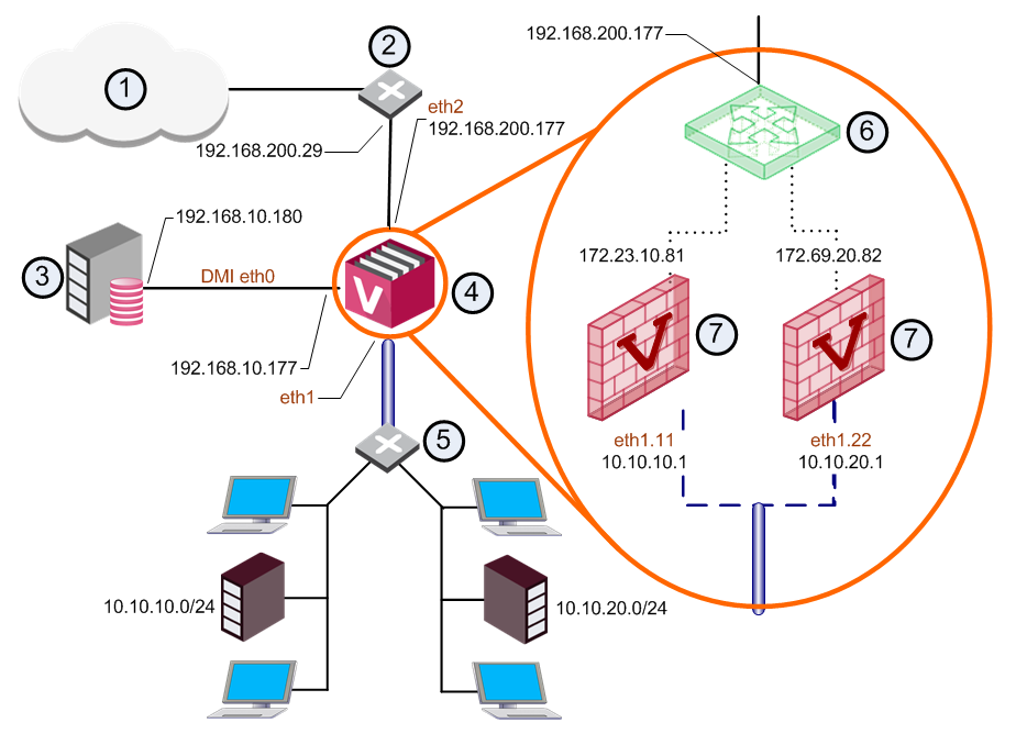
1 |
Internet |
|
6 |
External Virtual Router |
|
2 |
Router |
|
7 |
Virtual Systems |
|
3 |
|
|
VLAN Interface |
|
|
4 |
|
|
VLAN Trunk |
|
|
5 |
VLAN switch |
|
|


An external Virtual Router functions as the external gateway for Virtual Systems, allowing them to share a single secure physical interface leading to external networks and the Internet.
|
Item |
Description |
|
Item |
Description |
|---|---|---|---|---|
|
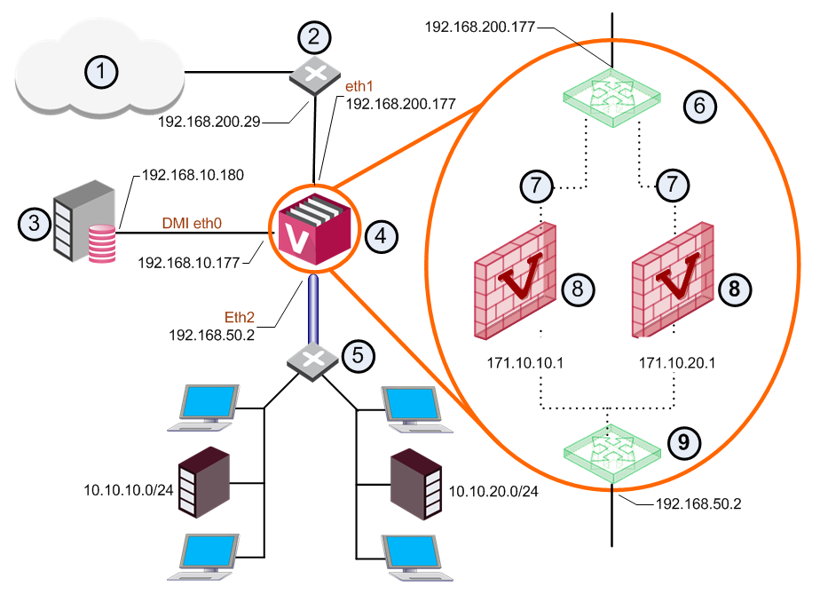
1 |
Internet |
|
7 |
Unnumbered |
|
2 |
Router |
|
8 |
Virtual Systems |
|
3 |
|
9 |
Internal Virtual Router |
|
|
4 |
|
|
VLAN Interface |
|
|
5 |
Switch |
|
|
VLAN Truck |
|
6 |
External Virtual Router |
|
|
Warp link |
In this scenario, VSX creates Warp interfaces between the Virtual Systems and both Virtual Routers. Note that the external Virtual System![]() Virtual Device on a VSX Gateway or VSX Cluster Member that implements the functionality of a Security Gateway. Acronym: VS. interfaces are defined as unnumbered interfaces.
Virtual Device on a VSX Gateway or VSX Cluster Member that implements the functionality of a Security Gateway. Acronym: VS. interfaces are defined as unnumbered interfaces.
An internal Virtual Router typically connects with one interface leading to internal networks through a switch with additional Warp Links leading to other Virtual Systems located in the VSX Gateway.
After you create a new Virtual Router, add new interfaces to the Virtual Systems to connect to the Virtual Router.
Creating a New Virtual Router
Use the Virtual Router Wizard to create a new Virtual Router. You can modify the initial definition and configure advanced options after you complete the wizard.
On interfaces and routes, you can select the Propagate route to adjacent Virtual Devices option to broadcast the IP address to neighboring Virtual Devices. This option enables connectivity with these Virtual Devices.
To create a Virtual Router:
-
Connect with SmartConsole
 Check Point GUI application used to manage a Check Point environment - configure Security Policies, configure devices, monitor products and events, install updates, and so on. to the Security Management Server or Target Domain Management Server that manages the new Virtual System.
 -
From the left navigation panel, click Gateways & Servers.
-
Create a new Virtual Router object in one of these ways:
-
From the top toolbar, click the New (
 ) > VSX > New Virtual Router.
 -
In the top left corner, click Objects menu > More object types > Network Object > Gateways and Servers > VSX > New Virtual Router.
-
In the top right corner, click Objects Pane > New > More > Network Object > Gateways and Servers > VSX > Virtual Router.
The Virtual Router Wizard opens.
-
-
In the Name field, enter the name for the new Virtual Router.
-
In the VSX Gateway / Cluster field, select the applicable VSX Gateway or VSX Cluster
Two or more Security Gateways that work together in a redundant configuration - High Availability, or Load Sharing.. -
Click Next.
-
In the Interfaces section, click Add to add the interface, to which the Virtual Router connects.
-
In the Routes section, click Add to add the applicable network routes.
-
Optional: Click Add Default Route and configure the default route.
-
Click Next.
-
Click Finish.
Modifying a Virtual Router Definition
-
Connect with SmartConsole to the Security Management Server or Target Domain Management Server that manages the Virtual Router.
-
From the Gateways & Servers view or Object Explorer, double-click the Virtual Router object.
Virtual Router - General Properties
The General Properties page enables you change the Virtual Router IP address as well as to add comments and change the icon color as displayed in SmartConsole.
Virtual Router - Topology
The Virtual Router Network Configuration page defines the network topology for the Virtual Router. For an external interface, you define one or more shared external interfaces and a default gateway.
Topology is defined by these properties:
-
Interfaces: Add new interfaces, or modify or delete existing interfaces.
To add an interface, click New. The Interface Properties window opens. Select an interface from the list and define the IP address, net mask and other properties (see Working with Interface Definitions).
-
Routes: Add network routes between this Virtual Router, Virtual Systems, external network devices and network addresses. Some Warp Link routes are defined automatically and cannot be modified or deleted. You can manually add new routes as well as delete and modify non-Warp Link routes.
-
Add Default Route: Define the default route as an IP address or Virtual System.
-
Advanced Routing: Configure source-based routing rules. See Working with Source-Based Routing.
Deleting a Virtual Router
-
Connect with SmartConsole to the Security Management Server or Target Domain Management Server that manages the new Virtual Router.
-
From the Gateways & Servers view or Object Explorer, double-click the Virtual Router object.
-
From the left tree, click Topology.
-
In the Interfaces section, remove all interfaces.
-
Click OK.
-
Right-click the Virtual Router object and select Delete.
-
Click Yes in the confirmation box.
-
Publish the SmartConsole session.
Virtual Routers in Virtual System Load Sharing Mode
From R81, you can configure Virtual Routers in VSLS mode.