Bridge Mode
By implementing native Layer 2 bridging instead of IP routing, you can add Virtual Systems without adversely affecting the existing IP structure.
When in the Bridge mode![]() Security Gateway or Virtual System that works as a Layer 2 bridge device for easy deployment in an existing topology., Virtual System
Security Gateway or Virtual System that works as a Layer 2 bridge device for easy deployment in an existing topology., Virtual System![]() Virtual Device on a VSX Gateway or VSX Cluster Member that implements the functionality of a Security Gateway. Acronym: VS. interfaces do not require IP addresses.
Virtual Device on a VSX Gateway or VSX Cluster Member that implements the functionality of a Security Gateway. Acronym: VS. interfaces do not require IP addresses.
You can optionally assign an IP address to the Virtual System itself (not the interfaces) to enable Layer 3 monitoring, which provides network fault detection functionality.
VSX![]() Virtual System Extension. Check Point virtual networking solution, hosted on a computer or cluster with virtual abstractions of Check Point Security Gateways and other network devices. These Virtual Devices provide the same functionality as their physical counterparts. supports these Bridge mode models:
Virtual System Extension. Check Point virtual networking solution, hosted on a computer or cluster with virtual abstractions of Check Point Security Gateways and other network devices. These Virtual Devices provide the same functionality as their physical counterparts. supports these Bridge mode models:
-
Active/Active Bridge Mode: Provides redundancy while preventing undesirable loops between redundant switches.
-
Active/Standby Bridge Mode: Provides path redundancy and loop prevention, while offering seamless support for Virtual System Load Sharing
 VSX Cluster technology that assigns Virtual System traffic to different Active Cluster Members. Acronym: VSLS. and overcoming many of the limitations of STP.
Active/Active Bridge Mode (Spanning Tree Protocol)
The Spanning Tree Protocol is an industry standard technology to prevent loops in high-speed switched networks.
To use the STP Bridge mode, you must have STP deployed and properly configured on your network.
These STP Layer 2 protocols are supported:
-
802.1d
-
802.1q
-
802.1s
-
802.1w
-
PVST+
See your vendor documentation to learn how to deploy and configure STP on your network hardware.
Active/Standby Bridge Mode
The Active/Standby Bridge Mode enhances both:
-
High Availability (for significant improvements).
-
Virtual System Load Sharing (VSLS) in VSX Cluster
Two or more Security Gateways that work together in a redundant configuration - High Availability, or Load Sharing. environments (for throughput distributed among Virtual Systems).
Active/Standby Bridge Mode has these advantages:
-
Instantaneous failover.
-
Enhanced administrator control over bridge failover.
-
VSLS support.
-
VLAN translation.
The principal limitation of the Active/Standby Bridge Mode is that it breaks the STP tree structure.
|
|
Note - When configuring a Virtual System in the Active/Standby Bridge Mode, you should remove Virtual System VLANs from the STP database in the switches. This action prevents delays due to trunk interface failback. |

Three Layer Hierarchical Model
A three-layer hierarchical model is used in large, high-traffic network environments.
-
A core network, with high-speed backbone switches that direct traffic to and from the Internet and other external networks.
-
A distribution layer, with routers, for connectivity between the core and the access layer.
-
An access layer, with redundant LAN switches, that forward traffic to and from internal networks.
VSX in Active/Standby Bridge Mode is incorporated in the distribution layer, enforcing the security policy![]() Collection of rules that control network traffic and enforce organization guidelines for data protection and access to resources with packet inspection..
Collection of rules that control network traffic and enforce organization guidelines for data protection and access to resources with packet inspection..
The routers direct external traffic to the appropriate Virtual System through a segregated VLAN. Inspected traffic exits the Virtual System through a separate segregated VLAN, to the routers and then to internal destinations.
VLAN Shared Interface Deployment
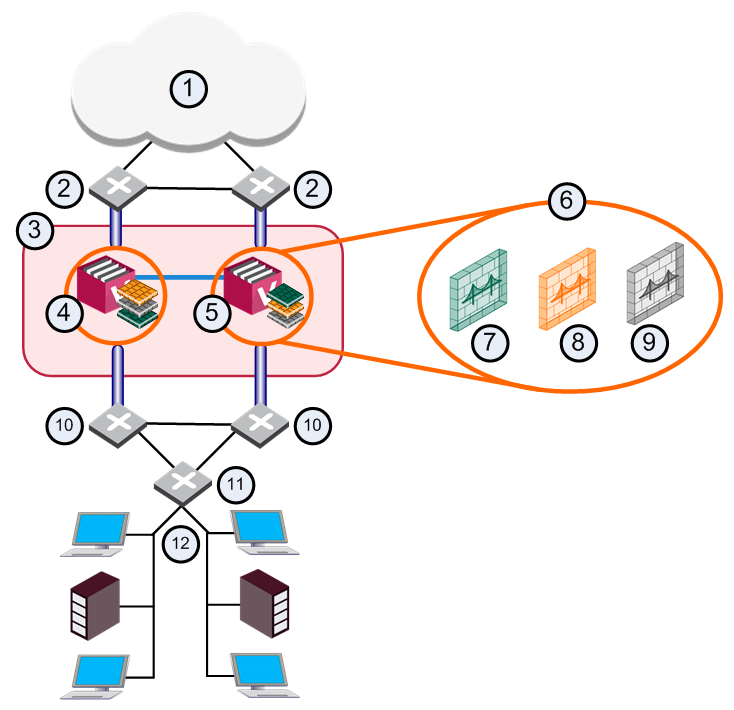
In this deployment, which cannot function using a standard STP Bridge mode configuration, each VSX Cluster Member![]() Security Gateway that is part of a cluster. connects to pair of redundant switches through a VLAN Trunk.
Security Gateway that is part of a cluster. connects to pair of redundant switches through a VLAN Trunk.
All Virtual Systems in a given VSX Cluster Member share the same VLAN Trunk.
|
Item |
Description |
|
Item |
Description |
|---|---|---|---|---|
|
1 |
Internet |
|
9 |
Virtual System 3 is Backup |
|
2 |
Redundant switches (external) |
|
10 |
Redundant switches (internal) |
|
3 |
VSX Cluster |
|
11 |
VLAN Switch |
|
4 |
VSX Cluster Member 1 |
|
12 |
Internal Networks |
|
5 |
VSX Cluster Member 2 |
|
|
Sync Network |
|
6 |
Virtual Systems in Bridge Mode |
|
|
Physical Interface |
|
7 |
Virtual System 1 is Active |
|
|
VLAN Trunk |
|
8 |
Virtual System 2 is Standby |
|
|
|


With Active/Standby Bridge Mode in High Availability mode, VSX Cluster directs traffic to VSX Cluster Members according to administrator-defined priorities and status.
In Virtual System Load Sharing deployments, the system distributes the traffic load amongst VSX Cluster Members according to the Virtual System Load Sharing configuration.