Advanced Configurations
This section describes Carrier Security advanced configurations.
GRX Redundant Deployment
Cellular operators strive to maintain 99.999% network availability. In this effort, they sometimes use two separate connections to the GRX (GPRS![]() General Packet Radio System, a non-voice value-added service for faster data transactions over a mobile telephone network, designed for deployment on GSM and TDMA-based mobile networks. GPRS overlays a packet-based air interface on the existing switched network. Roaming eXchange) network using two separate GRX providers on different sites.
General Packet Radio System, a non-voice value-added service for faster data transactions over a mobile telephone network, designed for deployment on GSM and TDMA-based mobile networks. GPRS overlays a packet-based air interface on the existing switched network. Roaming eXchange) network using two separate GRX providers on different sites.
This is somewhat similar to a dual ISP![]() Internet Service Provider - an organization or operator that sells Internet access. scenario, but with the difference that each GRX connection is set up in a different physical site protected by its own Carrier Security Gateway
Internet Service Provider - an organization or operator that sells Internet access. scenario, but with the difference that each GRX connection is set up in a different physical site protected by its own Carrier Security Gateway![]() Dedicated Check Point server that runs Check Point software to inspect traffic and enforce Security Policies for connected network resources.. The demanded availability requires all UMTS
Dedicated Check Point server that runs Check Point software to inspect traffic and enforce Security Policies for connected network resources.. The demanded availability requires all UMTS![]() Universal Mobile Telephone System, a third generation service (part of the IMT-2000 vision) that is expected to enable cellular service providers to deliver high-value broadband information, commerce and entertainment services to mobile users via fixed, wireless and satellite networks./LTE
Universal Mobile Telephone System, a third generation service (part of the IMT-2000 vision) that is expected to enable cellular service providers to deliver high-value broadband information, commerce and entertainment services to mobile users via fixed, wireless and satellite networks./LTE![]() Long Term Evolution - a standard for wireless broadband communication for mobile devices and data terminals, based on the GSM/EDGE and UMTS/HSPA technologies. It increases the capacity and speed using a different radio interface together with core network improvements. connections to survive in the event that one of these GRX connections will fail. For that reason, the cellular operator needs to synchronize the kernel state tables between the two Carrier Security gateways which are situated on physically distant locations. This requires the synchronization traffic to be transported over a wide area network (WAN). Synchronization traffic originally was designed to pass between cluster
Long Term Evolution - a standard for wireless broadband communication for mobile devices and data terminals, based on the GSM/EDGE and UMTS/HSPA technologies. It increases the capacity and speed using a different radio interface together with core network improvements. connections to survive in the event that one of these GRX connections will fail. For that reason, the cellular operator needs to synchronize the kernel state tables between the two Carrier Security gateways which are situated on physically distant locations. This requires the synchronization traffic to be transported over a wide area network (WAN). Synchronization traffic originally was designed to pass between cluster![]() Two or more Security Gateways that work together in a redundant configuration - High Availability, or Load Sharing. members only on a Local Area Network (LAN). Here we present a method that has been validated to work well to synchronize the Carrier Security cluster members over a Wide Area Network, and maintain full uptime and security for all PDP
Two or more Security Gateways that work together in a redundant configuration - High Availability, or Load Sharing. members only on a Local Area Network (LAN). Here we present a method that has been validated to work well to synchronize the Carrier Security cluster members over a Wide Area Network, and maintain full uptime and security for all PDP![]() Packet Data Protocol - a network protocol used by an external packet data network (usually IP). contexts during a "GRX failover". Uptime and security is maintained for PDP Contexts that existed before the failover occurred, and for the new ones that were initiated after the failover occurred. All PDP Contexts are maintained and secured during the failback as well.
Packet Data Protocol - a network protocol used by an external packet data network (usually IP). contexts during a "GRX failover". Uptime and security is maintained for PDP Contexts that existed before the failover occurred, and for the new ones that were initiated after the failover occurred. All PDP Contexts are maintained and secured during the failback as well.
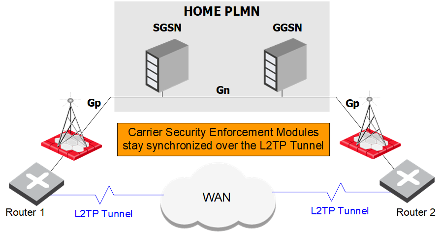
The basic idea behind the solution presented here is to deploy a Layer 2 tunnel between the two Carrier Security Gateways, which allows the Carrier Security cluster members to operate normally, as if they were on the same LAN, even though the Layer 2 tunnel traffic is being routed over a WAN network.
Asymmetric Routing
This solution works for both symmetric and asymmetric routing. Asymmetric routing takes place when some of the packets of a certain PDP session pass through one GRX, while other packets of the same PDP Context pass through another GRX. This can take place in either direction, i.e., to or from the partner.
In this deployment, asymmetric routing can be manifested in a few ways:
-
A GTP
 GPRS Tunnel Protocol. Create Request passes through GRX-A, and the corresponding GTP Create Response returns through GRX-B.
 -
Same as #1 for Update, Delete, Echo exchanges.
-
T-PDU
An original packet from an MS or a network node in an external packet data network. traffic may be split between GRX-A and GRX-B, in both directions (to and from the partner).
Asymmetric routing is supported by holding critical packets at the receiving Gateway until the peer gateway has acknowledged that it its information on these packets is in sync. This is true, for example, for all Request type messages, since the peer Gateway must register a Request packet before the corresponding Response message arrives.
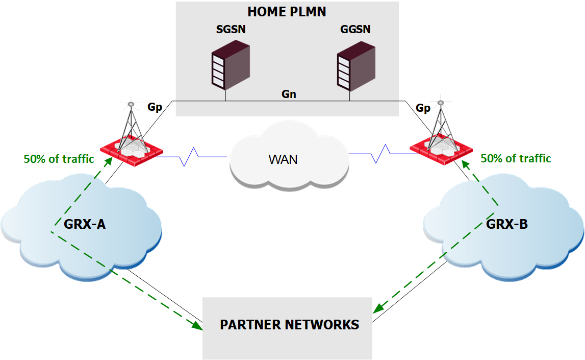
During normal operation, traffic is load-shared between the two GRXs, and consequently load-shared between the two Carrier Security Gateways. The traffic flow is according to the operator routing settings.
GRX load sharing during normal operation:
If any point on the network of one of the GRXs should fail, all traffic takes the path of the second, fully-functional GRX.
Traffic failover during GRX failure:
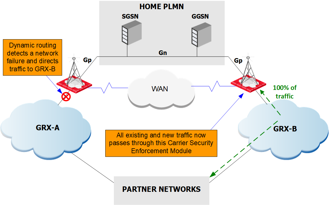
The path change occurs via dynamic routing settings using OSPF, BGP, etc. The data remains synchronized between the two Gateways.
Configuring a GRX Redundant Deployment
The distributed Carrier Security cluster consists of two Carrier Security Gateways.
Note - It is likely that more than two Carrier Security Gateways in such a deployment will work as well (e.g., in a deployment with three GRX connections), although this has not been verified.
-
Define a Carrier Security cluster, using 3rd Party HA mode, and add cluster members.
-
Set up the cluster to support non sticky connections, which enables the proper handling of asymmetric routing flows.
-
Set up a Layer 2 tunnel, such as L2TP, GRE, etc., between the two Carrier Security Gateways. The interfaces on both Gateways constituting the sync network should connect to the Layer 2 tunneling device on a LAN (or crossover cable).
Synchronizing Carrier Security over a WAN:
-
If desired, and the Layer 2 tunneling device supports it, establish encryption on the Layer 2 tunnel.
-
On the interfaces of the sync network, set the MTU to
1400. A value higher than 1400 may cause PMTU discovery procedures not supported by the tunneling device.
Testing the Setup
Perform the tests below to verify that the synchronization over the WAN network is operating properly.
-
Check on each Carrier Security member that it can see the other member over Layer 2. This is done by running the command
arp -aon one member, and verifying that it displays the MAC address of the other member. This will indicate that the Layer 2 tunnel is set up correctly. -
Using tools such as
tcpdump,fw monitor, etc., verify that sync traffic is being transmitted on the sync network. -
Verify the health of the sync mechanism by checking the output of the command
cphaprob statandcphaprob [-reset] syncstat. Refer to the ClusterXL User Guide included on the CD for details on the output of these commands. -
Verify that the GTP kernel tables are synchronized between the 2 members after passing some GTP traffic between them. Use the command
fw tab -s | grep gtpand compare the results. In general both members should show the same values for the tables. Slight differences are acceptable. -
Simulate failover by either shutting down a gateway and/or diverting all traffic to the other GRX path. In all cases, existing and new PDP contexts should remain intact.
-
Perform a reboot of Carrier Security member and verify that existing and new PDP Contexts remain intact.
-
Perform tests of asymmetric routing by setting up such routes in your network.
Fine-tuning Cluster Synchronization Parameters
For suggestions for fine tuning synchronization parameters, see the R81 ClusterXL Administration Guide.
Stripping Information Elements
In situations where an operator has advanced GSNs, using up-to-date or preliminary Information Elements, it may occur that a partner of this operator will have a GTP-aware firewall that drops these messages. This is due to the "suspicious" nature of firewalls to "unknown" traffic.
Carrier Security can be configured to strip specific Information Elements for GTP messages exchanged with specific partners in order to avoid cases where the firewall of the partner will drop the message. Today this already has potential relevancy for the following Information Elements:
-
IMEI-SV
-
User Location Information
-
RAT
-
Time Zone
To strip Information Elements from traffic destined for specific partners, do the following:
-
Create a new GTP v2 service as detailed in Enforcing a More Granular GTP Security Policy and select Save.
-
Open the GuiDBedit tool. Go to Services > services, and select the new service.
-
In the variables list, select the field stripped_information_elements and insert the numeric values of the Information Elements you want to remove. The delimiter can be either ',' (comma) or ' ' (space). Valid values for the Information Elements are from 1-30 (TV Information Elements), 116-127 (TV reserved Information Elements - they are all reserved accept 127 that is in use), and 128 - 255 (TLV Information Elements).
For example, if you want to strip the RAT and IMEI Information Elements enter:
151, 154
Note - If the input is illegal, the policy will not install.
-
Save and close GuiDBedit.
-
Add the new service to the Security Rule Base
All rules configured in a given Security Policy. Synonym: Rulebase. for the partner(s) for whom you want to strip the IEs, and install policy. The selected Information Elements will be removed from traffic to the selected partner(s).
Capacity Management
GTP Tunnel Capacity
Tunnel capacity is configured per gateway object in the Carrier Security pane of the gateway object properties. By default, tunnel capacity is set to automatic.
GTP Tunnels Aggressive Aging
Aggressive aging for GTP tables monitors the gateway for two main indicators to determine the system's capability to accept new GTP tunnels:
-
Amount of GTP tunnels already established in the gtp_tunnels table
-
Free system memory
When the gateway detects one of the indicators exceeding the upper thresholds, the system will activate aggressive aging. While active, the gateway will attempt to delete idle GTP tunnels from the gtp_tunnels table before recording new tunnels.
Fine Tuning
While the default values should fit most scenarios and deployments, you can change them to address conditions such as an expected high load on a roaming gateway. These default values can be changed in the Global Properties window.
|
Parameter |
Default / Min / Max value |
Description |
|---|---|---|
|
Aggressive aging |
0 |
Enables Aggressive Aging |
|
Aggressive Timeout |
3600 |
Duration in seconds before a tunnel is considered idle and eligible for deletion. |
|
Tunnel activation threshold |
80 / 0 / 100 |
Upper thresholds for activating aggressive aging. When tunnel amount or memory usage exceeds theses values (as a percent from the respective limits) - aggressive aging is activated.
|
|
Memory activation threshold |
80 / 0 / 100 |
|
|
Tunnel de-activation threshold |
60 / 0 / 100 |
Lower thresholds for deactivating aggressive aging. When tunnel amount or memory usage drop below theses values aggressive aging is deactivated.
|
|
Memory de-activation threshold |
60 / 0 / 100 |
Note - These guidelines are enforced and verified by SmartConsole![]() Check Point GUI application used to manage a Check Point environment - configure Security Policies, configure devices, monitor products and events, install updates, and so on. before a policy is pushed to the gateway:
Check Point GUI application used to manage a Check Point environment - configure Security Policies, configure devices, monitor products and events, install updates, and so on. before a policy is pushed to the gateway:
-
Thresholds
The upper threshold must be lower than a hundred and greater than the lower threshold which must be greater than a zero.
If a threshold is not within the permitted range, both upper and lower thresholds for the category (tunnel count or memory) are reset to the default values.
-
Aggressive time-out
The gtp_tunnels table time out must be greater than the gtp_aggr timeout which must be greater than the cphwd_gtp_refresh_interval x 1.5
If the aggressive timeout is not within the range it will be corrected automatically to a valid value.
SCTP
SCTP![]() Stream Control Transmission Protocol, SCTP was defined as a transport protocol for SS7 messages to be transmitted over IP networks. offers greater reliability over other transport layer protocols (such as UDP and TCP) by supporting multiple IP paths (multihoming) to a peer endpoint. For each multihomed SCTP endpoint, multiple IP addresses serve each SCTP association.
Stream Control Transmission Protocol, SCTP was defined as a transport protocol for SS7 messages to be transmitted over IP networks. offers greater reliability over other transport layer protocols (such as UDP and TCP) by supporting multiple IP paths (multihoming) to a peer endpoint. For each multihomed SCTP endpoint, multiple IP addresses serve each SCTP association.
Note - You can create one rule![]() Set of traffic parameters and other conditions in a Rule Base (Security Policy) that cause specified actions to be taken for a communication session. for an SCTP connection, but for each multihomed endpoint you must create a group of IP addresses associated with the connection.
Set of traffic parameters and other conditions in a Rule Base (Security Policy) that cause specified actions to be taken for a communication session. for an SCTP connection, but for each multihomed endpoint you must create a group of IP addresses associated with the connection.
In case of failover, each new active connection is checked for access policy and state. A new active connection is not automatically accepted because of an existing association.
SCTP Supported Features
SCTP fully complies with RFC4960, which describes the Stream Control Transmission Protocol, and supports these features:
-
SCTP stateless verification - makes sure that each SCTP packet complies with RFC 4960 regardless of the packet's state.
-
SCTP stateful inspection - accepts SCTP packets according to the association state.
-
Support for multihomed SCTP - opens multiple child connections under the established association.
-
SCTP packet filtering - filters for access control through policy rule definition.
-
SCTP with static NAT.
-
SCTP Acceleration.
Configuring SCTP Inspection
When a Carrier license is installed, you can specify SCTP services in your Firewall rules. SCTP Inspection occurs in these cases:
-
There is a match on a rule containing an SCTP or Diameter
An authentication, authorization and accounting protocol that has many features not included in the legacy RADIUS protocol. SCTP service in the Service cell. -
There is a match on a rule with Service= Any and this SCTP service has Match for any selected.
To activate SCTP Inspection:
-
Open SmartConsole.
-
In Objects > Object Explorer click New > Service > SCTP.
On the General page configure:
-
Name - The name of the service. The name assigned here must be the same as the server service name (as in the services file). If NIS is used, the firewall automatically retrieves the information from NIS.
-
Port - The number of the port that gives this service.
-
-
Click Advanced and configure:
The Advanced SCTP Service Properties window opens.
-
Source Port - Port number for the client side service. If specified, only those Source port Numbers will be Accepted, Dropped, or Rejected during packet inspection. Otherwise, the source port is not inspected.
-
Keep connections open after policy has been installed - If the connections are not allowed in the new policy, they are still kept. This overrides the settings in the Connection Persistence page. If you change this property, the change does not have effect on open connections, but only future connections.
-
Enable Aggressive Aging - Sets short (aggressive) timeouts for idle connections. When a connection is idle for more than its aggressive timeout value, it is marked as
eligible for deletion. When memory consumption or connections table capacity exceeds a user-defined threshold (high watermark), aggressive aging starts. Each incoming connection starts to deletek(10 by default) connections that are eligible for deletion. This continues until memory consumption or connections capacity decreases below the low value. -
Synchronize connections if State Synchronization is enabled on cluster - Enables state-synchronized High Availability or Load Sharing on a ClusterXL or OPSEC-certified cluster. Of the services allowed by the Rule Base, only those with Synchronize connections on cluster selected are synchronized as they go through the cluster. By default, all new and existing services are synchronized.
-
-
Click OK.
-
Open Global properties > Stateful Inspection.
Configure these Stateful Inspection options:
|
Option |
Meaning |
|---|---|
|
SCTP start timeout |
|
|
SCTP session timeout |
|
|
SCTP end timeout |
|
Configure these options for Out of state packets:
|
Option |
Meaning |
|---|---|
|
Drop out of state SCTP packets |
|
|
Log on drop |
|
To deactivate out of state packet drop with SmartConsole:
-
In SmartConsole, go to Global properties > Stateful Inspection.
-
Clear the Drop out of state SCTP packets option.
-
Save and install the policy.
To deactivate packet inspection with GuiDBedit:
-
Open GuiDBedit.
-
Search for:
fw_sctp_packet_inspection. -
Set the property to false.
-
Save the database and install policy.
Configuring SCTP Acceleration
To enable SCTP acceleration, run this command on the Security Gateway or cluster member![]() Security Gateway that is part of a cluster.:
Security Gateway that is part of a cluster.:
sim feature sctp on
To disable SCTP acceleration, run this command on the Security Gateway or cluster member:
sim feature sctp off
Note -If SCTP acceleration is activated and SCTP inspection is deactivated, the Performance Pack accelerates all SCTP packet types.
Configuring SCTP NAT
SCTP NAT overrides the currently defined NAT policy. When this feature is not activated, SCTP connections do not use NAT.
To activate SCTP NAT, run this command on the Security Gateway:
fw ctl set int fwx_enable_sctp_nat 1
To deactivate SCTP NAT, run this command on the Security Gateway:
fw ctl set int fwx_enable_sctp_nat 0