Virtual System in Bridge Mode
Core Network Security
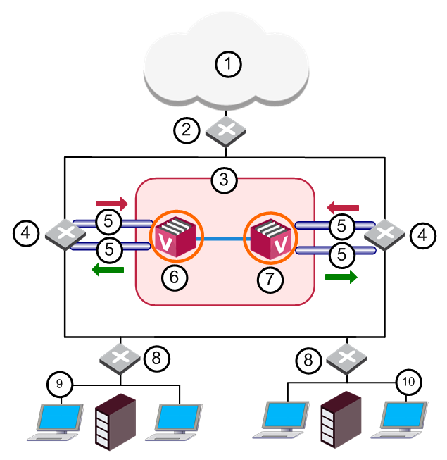
Many Enterprise environments are based on core networks. Situated adjacent to core network backbone switches, VSX![]() Virtual System Extension. Check Point virtual networking solution, hosted on a computer or cluster with virtual abstractions of Check Point Security Gateways and other network devices. These Virtual Devices provide the same functionality as their physical counterparts. protects the internal network by providing security at Layer 2, Layer 3 or both. VSX communicates with the core network using the existing infrastructure. With Virtual Systems in the Bridge Mode
Virtual System Extension. Check Point virtual networking solution, hosted on a computer or cluster with virtual abstractions of Check Point Security Gateways and other network devices. These Virtual Devices provide the same functionality as their physical counterparts. protects the internal network by providing security at Layer 2, Layer 3 or both. VSX communicates with the core network using the existing infrastructure. With Virtual Systems in the Bridge Mode![]() Security Gateway or Virtual System that works as a Layer 2 bridge device for easy deployment in an existing topology., VSX can protect departmental networks, while simultaneously preventing network segmentation. In this case, switches are located at the entrance to each department's network.
Security Gateway or Virtual System that works as a Layer 2 bridge device for easy deployment in an existing topology., VSX can protect departmental networks, while simultaneously preventing network segmentation. In this case, switches are located at the entrance to each department's network.
|
Item |
Description |
|
Item |
Description |
|---|---|---|---|---|
|
1 |
Internet |
|
8 |
LAN Switches |
|
2 |
Core Network Backbone switch |
|
9 |
Sales |
|
3 |
|
10 |
Finance |
|
|
4 |
Router |
|
|
Sync Network |
|
5 |
VLAN |
|
|
Physical Interface |
|
6 |
Member 1 |
|
|
VLAN Trunk |
|
7 |
Member 2 |
|
|
|


VSX ensures connectivity between the core network and the Internet or external networks, while providing perimeter security.
Security can be configured on a per VLAN basis.
Configuring Virtual Systems for the Active/Standby Bridge Mode
To configure a Virtual System![]() Virtual Device on a VSX Gateway or VSX Cluster Member that implements the functionality of a Security Gateway. Acronym: VS. in Bridge Mode, configure it as such when you first create the Virtual System object.
Virtual Device on a VSX Gateway or VSX Cluster Member that implements the functionality of a Security Gateway. Acronym: VS. in Bridge Mode, configure it as such when you first create the Virtual System object.
You cannot reconfigure a non-Bridge Mode Virtual System to use the Bridge Mode later.
To configure a Virtual System for the Active/Standby Bridge Mode:
-
In the Virtual System General Properties page of the new Virtual System object, select Bridge Mode.
-
Click Next.
The Virtual System Network Configuration window opens.
-
Configure the external and internal interfaces for the Virtual System.
-
Optional: Select Enable Layer 3 Bridge Interface Monitoring.
The IP address must be unique and on the same subnet as the protected network.
-
Click Next.
-
Click Finish.
Separate Interfaces in the Bridge Mode
To configure the external and internal interfaces:
-
Select the applicable interfaces for the internal and external networks from the appropriate list.
If the selected Interface is a VLAN interface, enter the same VLAN tag in both the external and internal VLAN Tag fields. This field is not available for non-VLAN interfaces.
-
Configure the topology for the internal interface:
-
Select Not Defined if you do not wish to configure an IP address.
-
Select Specific and then select an IP address definition from the list. IP address definitions can be based on object groups or predefined networks that configure the topology.
-
-
To create a new IP address definition:
-
Select Specific, and click New.
-
Select Group to configure an object group, or Network to configure network properties.
-
-
Enable Layer 3 bridge interface monitoring to enable Layer 3 network fault detection for this Virtual System.
Enter an IP address and subnet mask, which continuously monitors the specified network for faults or connectivity issues. The IP address/Subnet mask configure the network, on which the Virtual System resides.
-
Complete the definition process.
Multi Bridge Interfaces
This feature is supported for VSX Gateways and VSX Clusters in the Active/Active Bridge Mode.
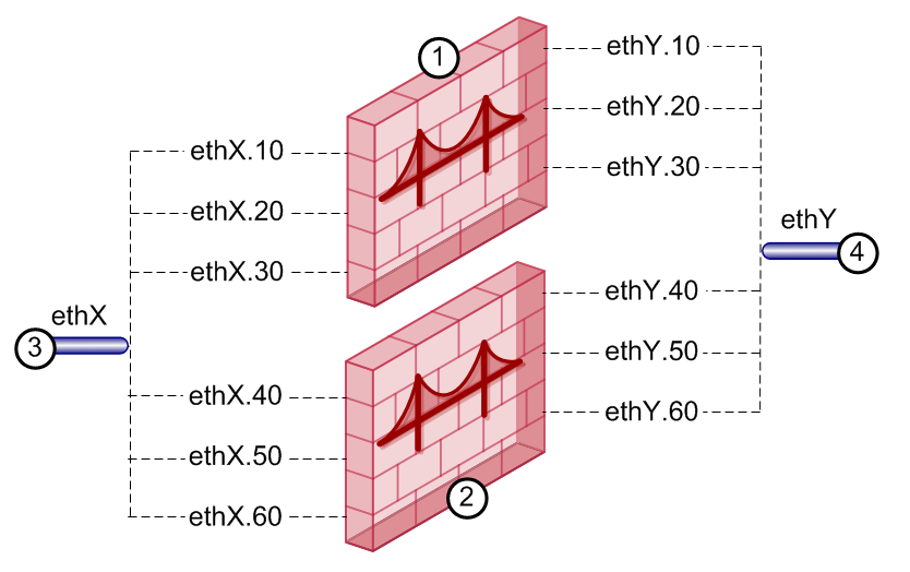
Multi Bridge allows traffic from many different VLANs to move through one Virtual System in the Bridge Mode.
In a Virtual System in the Bridge Mode, you can add physical and VLAN interfaces.
When you add more than two VLAN interfaces, Multi Bridge is automatically enabled.
Configure the same VLAN tag on each set of two interfaces to make them bridged.
Requirements for Multi Bridge interfaces:
-
All interfaces must be VLANs.
-
You can make multiple bridges only between two VLAN Trunks.
-
You can add up to 64 pairs of VLAN interfaces for one Multi Bridge.
-
Those two VLAN Trunks must be used together, and not with other VLAN Trunks, in other Virtual Systems in Bridge Mode or Multi Bridges.
For example, you configure
eth1.10,eth2.10,eth1.20,eth2.20.Now the VLAN Trunks,
eth1andeth2, cannot be used with other VLAN Trunks on other Virtual Systems in Bridge Mode:eth1.30cannot bridge witheth3.30.
|
Item |
Description |
|---|---|
|
1 |
Virtual System in Bridge Mode with three bridges on VLAN interfaces with tags 10, 20, and 30. |
|
2 |
Virtual System in Bridge Mode with three bridges on VLAN interfaces with tags 40, 50, and 60. |
|
3 |
VLAN Trunks. Each must be paired with the other in all bridges, or used without bridging. They cannot be paired with a different VLAN Trunk. |
|
|
Note - Names of Multi Bridge interfaces have a template " |

To configure a new Multi Bridge:
-
Connect with SmartConsole
 Check Point GUI application used to manage a Check Point environment - configure Security Policies, configure devices, monitor products and events, install updates, and so on. to the Security Management Server Dedicated Check Point server that runs Check Point software to manage the objects and policies in a Check Point environment within a single management Domain. Synonym: Single-Domain Security Management Server. or Target Domain Management Server Check Point Single-Domain Security Management Server or a Multi-Domain Security Management Server. used to manage the new Virtual System.
 -
From the left navigation panel, click Gateways & Servers.
-
Create a new Virtual System object in one of these ways:
-
From the top toolbar, click the New (
 ) > VSX > New Virtual System.
 -
In the top left corner, click Objects menu > More object types > Network Object > Gateways and Servers > VSX > New Virtual System.
-
In the top right corner, click Objects Pane > New > More > Network Object > Gateways and Servers > VSX > Virtual System.
-
-
In the Name field, enter the name for the new Virtual System.
-
In the VSX Gateway / Cluster field, select the applicable VSX Gateway
Physical server that hosts VSX virtual networks, including all Virtual Devices that provide the functionality of physical network devices. It holds at least one Virtual System, which is called VS0. or VSX Cluster. -
Select Bridge Mode.
-
Click Next.
-
In the Interfaces section, click Add to add the first VLAN interface for the bridge.
-
In the Interfaces section, click Add again to add the second VLAN interface for the bridge.
-
In the Interfaces section, add more VLAN interface pairs to the Multi Bridge in the same way.
Make sure the interfaces in each pair have the same VLAN tag, from different interfaces.
For example:
eth2.50,eth2.51eth3.50,eth3.51Make sure to use the same two VLAN Trunks.
-
Click Next.
-
Click Finish.
-
Install the applicable Access Control Policy on the new Virtual System object.
To convert a Bridge to a Multi Bridge:
-
Connect with SmartConsole to the Security Management Server or Target Domain Management Server used to manage the Virtual System in the Bridge Mode.
-
From the left navigation panel, click Gateways & Servers.
-
Double-click the Virtual System object.
-
From the left tree, click Bridge Configuration > Topology.
-
In the Interfaces section, if there are physical interfaces in the Interfaces list, remove them.
-
In the Interfaces section, add more VLAN interface pairs to the Multi Bridge.
-
Click OK.
-
Install the applicable Access Control Policy on the Virtual System object.