Route Based VPN
Overview of Route-based VPN
The use of VPN Tunnel![]() An encrypted connection between two hosts using standard protocols (such as L2TP) to encrypt traffic going in and decrypt it coming out, creating an encapsulated network through which data can be safely shared as though on a physical private line. Interfaces (VTI) is based on the idea that setting up a VTI between peer Security Gateways is similar to connecting them directly.
An encrypted connection between two hosts using standard protocols (such as L2TP) to encrypt traffic going in and decrypt it coming out, creating an encapsulated network through which data can be safely shared as though on a physical private line. Interfaces (VTI) is based on the idea that setting up a VTI between peer Security Gateways is similar to connecting them directly.
A VTI is a virtual interface that can be used as a Security Gateway![]() Dedicated Check Point server that runs Check Point software to inspect traffic and enforce Security Policies for connected network resources. to the VPN domain of the peer Security Gateway. Each VTI is associated with a single tunnel to a Security Gateway. The tunnel itself with all of its properties is defined, as before, by a VPN Community
Dedicated Check Point server that runs Check Point software to inspect traffic and enforce Security Policies for connected network resources. to the VPN domain of the peer Security Gateway. Each VTI is associated with a single tunnel to a Security Gateway. The tunnel itself with all of its properties is defined, as before, by a VPN Community![]() A named collection of VPN domains, each protected by a VPN gateway. linking the two Security Gateways. Configure the peer Security Gateway with a corresponding VTI. The native IP routing mechanism on each Security Gateway can then direct traffic into the tunnel as it would for other interfaces.
A named collection of VPN domains, each protected by a VPN gateway. linking the two Security Gateways. Configure the peer Security Gateway with a corresponding VTI. The native IP routing mechanism on each Security Gateway can then direct traffic into the tunnel as it would for other interfaces.
All traffic destined to the VPN domain of a peer Security Gateway is routed through the "associated" VTI. This infrastructure allows dynamic routing protocols to use VTIs. A dynamic routing protocol daemon running on the Security Gateway can exchange routing information with a neighboring routing daemon running on the other end of an IPsec tunnel, which appears to be a single hop away.
Route Based VPN can only be implemented between Security Gateways within the same VPN community.
To deploy Route Based VPN, Directional Rules have to be configured in the Rule Base![]() All rules configured in a given Security Policy. Synonym: Rulebase. of the Security Management Server
All rules configured in a given Security Policy. Synonym: Rulebase. of the Security Management Server![]() Dedicated Check Point server that runs Check Point software to manage the objects and policies in a Check Point environment within a single management Domain. Synonym: Single-Domain Security Management Server.. See Directional Enforcement within a Community
Dedicated Check Point server that runs Check Point software to manage the objects and policies in a Check Point environment within a single management Domain. Synonym: Single-Domain Security Management Server.. See Directional Enforcement within a Community
VPN Tunnel Interface (VTI)
A VPN Tunnel Interface is a virtual interface on a Security Gateway that is related to a VPN tunnel and connects to a remote peer. You create a VTI on each Security Gateway that connects to the VTI on a remote peer. Traffic routed from the local Security Gateway via the VTI is transferred encrypted to the associated peer Security Gateway.
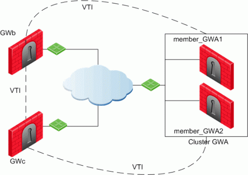
In this scenario:
-
There is a VTI connecting "Cluster
 Two or more Security Gateways that work together in a redundant configuration - High Availability, or Load Sharing. GWa" and "GWb" (you must configure the same Tunnel ID on these peers)
 -
There is a VTI connecting "Cluster GWa" and "GWc" (you must configure the same Tunnel ID on these peers)
-
There is a VTI connecting "GWb" and "GWc" (you must configure the same Tunnel ID on these peers)
A virtual interface behaves like a point-to-point interface directly connected to the remote peer. Traffic between network hosts is routed into the VPN tunnel with the IP routing mechanism of the Operating System. Security Gateway objects are still required, as well as VPN communities (and access control policies) to define which tunnels are available. However, VPN encryption domains for each peer Security Gateway are no longer necessary. The decision whether or not to encrypt depends on whether the traffic is routed through a virtual interface. The routing changes dynamically if a dynamic routing protocol (OSPF/BGP) is available on the network.
When a connection that originates on GWb is routed through a VTI to GWc (or servers behind GWc) and is accepted by the implied rules, the connection leaves GWb in the clear with the local IP address of the VTI as the source IP address. If this IP address is not routable, return packets will be lost.
The solution for this issue is:
-
Configure a static route on GWb that redirects packets destined to GWc from being routed through the VTI
-
Not including it in any published route
-
Adding route maps that filter out GWc's IP addresses
Having excluded those IP addresses from route-based VPN, it is still possible to have other connections encrypted to those addresses (i.e. when not passing on implied rules) by using domain based VPN definitions.
The VTI can be configured in two ways:
|
VTI Type |
Description |
|---|---|
|
Numbered |
You configure a local and remote IP address for each numbered VPN Tunnel Interface (VTI). For each Security Gateway, you configure a local IP address, a remote address, and the local IP address source for outbound connections to the tunnel. The remote IP address must be the local IP address on the remote peer Security Gateway. More than one VTI can use the same IP Address, but they cannot use an existing physical interface IP address. |
|
Unnumbered |
For unnumbered VTIs, you define a proxy interface for each Security Gateway. Each Security Gateway uses the proxy interface IP address as the source for outbound traffic. Unnumbered interfaces let you assign and manage one IP address for each interface. Proxy interfaces can be physical or loopback interfaces. |
Using Dynamic Routing Protocols
VTIs allow the ability to use Dynamic Routing Protocols to exchange routing information between Security Gateways.
The Dynamic Routing Protocols supported on Gaia![]() Check Point security operating system that combines the strengths of both SecurePlatform and IPSO operating systems. are:
Check Point security operating system that combines the strengths of both SecurePlatform and IPSO operating systems. are:
-
BGP4
-
OSPFv2
-
RIPv1
-
RIPv2
VTIs in a Clustered Environment
When configuring numbered VTIs in a clustered environment, a number of issues need to be considered:
-
Each member must have a unique source IP address.
-
Every interface on each member requires a unique IP address.
-
All VTIs going to the same remote peer must have the same name.
-
Cluster IP addresses are required.
Configuring VTIs in Gaia Operating System
See the R80.40 Gaia Administration Guide > Chapter Network Management > Section Network Interfaces > Section VPN Tunnel Interfaces.
Note - For VTIs between Gaia Security Gateways and Cisco GRE gateways, you must manually configure the Hello/Dead packet intervals at 10/40 on the Gaia Security Gateways, or at 30/120 on the peer gateway. If not, OSPF is not able to get into the "FULL" state.
Enabling Route Based VPN
If you configure a Security Gateway for Domain Based VPN and Route Based VPN, Domain Based VPN takes precedence by default.
To force Route Based VPN to take priority, you must create a dummy (empty) group and assign it to the VPN domain.
To force Route-Based VPN to take priority:
-
In SmartConsole
Check Point GUI application used to manage a Check Point environment - configure Security Policies, configure devices, monitor products and events, install updates, and so on., from the left navigation panel, click Gateways & Servers. -
Open the Security Gateway / Cluster object.
-
From the left tree, click Network Management > VPN Domain.
-
Select Manually define.
-
Click the [...] button.
-
Click New > Group > Simple Group.
-
Enter a Name.
-
Click OK (leave this Group object empty).
Configuring Numbered VTIs - Example
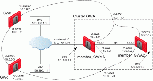
The Security Gateways in this scenario are:
|
Device Type |
Specific Computers |
|---|---|
|
ClusterXL |
Cluster GWa:
|
|
VPN peers |
|
VTIs connect these Security Gateways:
-
Members of "
Cluster GWa" and "GWb" -
Members of "
Cluster GWa" and "GWc" -
"
GWb" and "GWc"
IP Configuration:
|
Peer |
Type of IP Address and Interface |
IP Address / Netmask |
|---|---|---|
|
Cluster GWa |
External Unique IP address of |
170.170.1.1 / 24 |
|
member_GWa1 |
External VIP address of |
170.170.1.10 / 24 |
|
|
IP address of Sync interface |
5.5.5.1 / 24 |
|
|
IP address of VTI for " |
Local: 10.0.1.11 / 24 Remote: 10.0.0.2 / 24 |
|
|
VIP address of VTI for " |
10.0.1.10 / 24 |
|
|
IP address of VTI for " |
Local: 10.0.1.21 / 24 Remote: 10.0.0.3 / 24 |
|
|
VIP address of VTI for " |
10.0.1.20 / 24 |
|
Cluster GWa |
External Unique IP address of |
170.170.1.2 / 24 |
|
member_GWa2 |
External VIP address of |
170.170.1.10 / 24 |
|
|
IP address of Sync interface |
5.5.5.2 / 24 |
|
|
IP address of VTI for " |
Local: 10.0.1.12 / 24 Remote: 10.0.0.2 / 24 |
|
|
VIP address of VTI for " |
10.0.1.10 / 24 |
|
|
IP address of VTI " |
Local: 10.0.1.22 / 24 Remote: 10.0.0.3 / 24 |
|
|
VIP address of VTI for " |
10.0.1.20 / 24 |
|
GWb |
External Unique IP address of |
180.180.1.1 / 24 |
|
|
IP address of VTI for " |
Local: 10.0.0.2 / 24 Remote: 10.0.1.10 / 24 |
|
|
IP address of VTI " |
Local: 10.0.0.2 / 24 Remote: 10.0.0.3 / 24 |
|
GWc |
External Unique IP address of |
190.190.1.1 / 24 |
|
|
IP address of VTI for " |
Local: 10.0.0.3 / 24 Remote: 10.0.1.20 / 24 |
|
|
IP address of VTI for " |
Local: 10.0.0.3 / 24 Remote: 10.0.0.2 / 24 |
The example configurations below use the same Security Gateway names and IP addresses that are described in Numbered VTIs.
-
Configure the required VTIs on 'member_GWa1'
See the R80.40 Gaia Administration Guide > Chapter Network Management > Section Network Interfaces > Section VPN Tunnel Interfaces.
-
Configure a Numbered VPN Tunnel Interface for GWb.
Use these settings for the VTI:
Parameter
Value
VPN Tunnel ID
Integer from 1 to 99

Important - You must configure the same ID for GWb on all Cluster Members.
Peer
GWb
VPN Tunnel Type
Numbered
Local Address
10.0.1.11
Remote Address
10.0.0.2
-
Configure a Numbered VPN Tunnel Interface for GWc.
Use these settings for the VTI:
Parameter
Value
VPN Tunnel ID
Integer from 1 to 99
Important - You must configure the same ID for GWc on all Cluster Members.
Peer
GWc
VPN Tunnel Type
Numbered
Local Address
10.0.1.21
Remote Address
10.0.0.3
-
-
Configure the required VTIs on 'member_GWa2'
See the R80.40 Gaia Administration Guide > Chapter Network Management > Section Network Interfaces > Section VPN Tunnel Interfaces.
-
Configure a Numbered VPN Tunnel Interface for GWb.
Use these settings for the VTI:
Parameter
Value
VPN Tunnel ID
Integer from 1 to 99
Important - You must configure the same ID for GWb on all Cluster Members.
Peer
GWb
VPN Tunnel Type
Numbered
Local Address
10.0.1.12
Remote Address
10.0.0.2
-
Configure a Numbered VPN Tunnel Interface for GWc.
Use these settings for the VTI:
Parameter
Value
VPN Tunnel ID
Integer from 1 to 99
Important - You must configure the same ID for GWc on all Cluster Members.
Peer
GWc
VPN Tunnel Type
Numbered
Local Address
10.0.1.22
Remote Address
10.0.0.3
-
-
Configure the required VTIs on 'GWb'
See the R80.40 Gaia Administration Guide > Chapter Network Management > Section Network Interfaces > Section VPN Tunnel Interfaces.
-
Configure a Numbered VPN Tunnel Interface for Cluster GWa.
Use these settings for the VTI:
Parameter
Value
VPN Tunnel ID
Integer from 1 to 99
Important - You must configure the same ID you configured on all Cluster Members for GWb.
Peer
ClusterGWa
VPN Tunnel Type
Numbered
Local Address
10.0.0.2
Remote Address
10.0.1.10
-
Configure a Numbered VPN Tunnel Interface for GWc.
Use these settings for the VTI:
Parameter
Value
VPN Tunnel ID
Integer from 1 to 99
Important - You must configure the same ID for this VTI on GWb and GWc.
Peer
GWc
VPN Tunnel Type
Numbered
Local Address
10.0.0.2
Remote Address
10.0.0.3
-
-
Configure the required VTIs on 'GWc'
See the R80.40 Gaia Administration Guide > Chapter Network Management > Section Network Interfaces > Section VPN Tunnel Interfaces.
-
Configure a Numbered VPN Tunnel Interface for Cluster GWa.
Use these settings for the VTI:
Parameter
Value
VPN Tunnel ID
Integer from 1 to 99
Important - You must configure the same ID you configured on all Cluster Members for GWc.
Peer
ClusterGWa
VPN Tunnel Type
Numbered
Local Address
10.0.0.3
Remote Address
10.0.1.20
-
Configure a Numbered VPN Tunnel Interface for GWb.
Use these settings for the VTI:
Parameter
Value
VPN Tunnel ID
Integer from 1 to 99
Important - You must configure the same ID for this VTI on GWc and GWb.
Peer
GWb
VPN Tunnel Type
Numbered
Local Address
10.0.0.3
Remote Address
10.0.0.2
-
-
Configure the Cluster object in SmartConsole
After configuring the VTIs on the cluster members, you must configure the Cluster Virtual IP addresses of these VTIs in the cluster object in SmartConsole.
-
From the left navigation panel, click Gateways & Servers.
-
Right-click the cluster object and select Edit.
-
From the left tree, click Network Management.
-
Click Get Interfaces > Get Interfaces Without Topology.
The VTIs appear in the Topology column as Point to point.
Interfaces are members of the same VTI if these criteria match:
-
Peer
-
Remote IP address
-
Interface name
-
-
Configure the Cluster Virtual IP addresses on the VTIs:
-
Select the VTI interface and click Edit.
-
On the General page, enter the Virtual IP address.
-
Click OK.
Virtual IP Addresses:
Name
Topology
Virtual IP
member_GWa1
member_GWa2
Comment
vpnt1
Point to point
10.0.1.10
10.0.1.11
10.0.1.12
VTI with GWb
vpnt2
Point to point
10.0.1.20
10.0.1.21
10.0.1.22
VTI with GWc
-
-
Click OK.
-
Install the Access Control Policy on the cluster object.
-
Enabling Dynamic Routing Protocols on VTIs - Example
The example below shows how the OSPF dynamic routing protocol is enabled on VTIs.
Note that the network commands for single members and cluster members are not the same.
For more information on VTIs and advanced routing commands, see the:
When peering with a Cisco GRE enabled device, a point to point GRE tunnel is required.
Configuration:
vpnt1 is the VTI between 'member_GWa1' and 'GWb'
vpnt2 is the VTI between 'member_GWa1' and 'GWc'
member_GWa1:0> set ospf area 0.0.0.0 on member_GWa1:0> set router-id 170.170.1.10 member_GWa1:0> set ospf interface vpnt1 area 0.0.0.0 on member_GWa1:0> set ospf interface vpnt2 area 0.0.0.0 on member_GWa1:0> set route-redistribution to ospf2 from kernel all-ipv4-routes on member_GWa1:0> save config member_GWa1:0> show configuration ospf |
vpnt1 is the VTI between 'member_GWa2' and 'GWb'
vpnt2 is the VTI between 'member_GWa2' and 'GWc'
member_GWa2:0> set ospf area 0.0.0.0 on member_GWa2:0> set router-id 170.170.1.10 member_GWa2:0> set ospf interface vpnt1 area 0.0.0.0 on member_GWa2:0> set ospf interface vpnt2 area 0.0.0.0 on member_GWa2:0> set route-redistribution to ospf2 from kernel all-ipv4-routes on member_GWa2:0> save config member_GWa2:0> show configuration ospf |
vpnt1 is the VTI between 'GWb' and 'Cluster GWa'
vpnt3 is the VTI between 'GWb' and 'GWc'
GWb:0> set ospf area 0.0.0.0 on GWb:0> set router-id 180.180.1.1 GWb:0> set ospf interface vpnt1 area 0.0.0.0 on GWb:0> set ospf interface vpnt3 area 0.0.0.0 on GWb:0> set route-redistribution to ospf2 from kernel all-ipv4-routes on GWb:0> save config GWb:0> show configuration ospf |
vpnt2 is the VTI between 'GWc' and 'Cluster GWa'
vpnt3 is the VTI between 'GWc' and 'GWb'
GWc:0> set ospf area 0.0.0.0 on GWc:0> set router-id 190.190.1.1 GWc:0> set ospf interface vpnt2 area 0.0.0.0 on GWc:0> set ospf interface vpnt3 area 0.0.0.0 on GWc:0> set route-redistribution to ospf2 from kernel all-ipv4-routes on GWc:0> save config GWc:0> show configuration ospf |
Configuring Anti-Spoofing on VTIs in SmartConsole
-
From the left navigation panel, click Gateways & Servers.
-
Right-click the Security Gateway object and select Edit.
-
From the left tree, click Network Management.
-
Select a VTI interface, and click Edit.
-
From the left tree, click General.
-
In the Topology section, click Modify.
-
In the IP Addresses behind peer Security Gateway that are within reach of this interface section, select:
-
Not Defined - To accept all traffic.
-
Specific - To choose a particular network. The IP addresses in this network will be the only addresses accepted by this interface.
-
-
In the Perform Anti-Spoofing based on interface topology section, select Don't check packets from to make sure Anti-Spoofing does not occur for traffic from IP addresses from certain internal networks to the external interface. Configure a Network object that represents those internal networks with valid addresses, and from the drop-down list, select that Network object.
Anti-Spoofing does not apply to objects selected in the Don't check packets from drop-down menu.
-
In the Spoof Tracking field, select the applicable options.
-
Click OK.
-
Install the Access Control Policy on the Security Gateway object.
Routing Multicast Packets Through VPN Tunnels
Multicast is used to transmit a single message to a select group of recipients. IP Multicasting applications send one copy of each datagram (IP packet) and address it to a group of computers that want to receive it. This technique addresses datagrams to a group of receivers (at the multicast address) rather than to a single receiver (at a unicast address). The network is responsible for forwarding the datagrams to only those networks that need to receive them. PIM is required for this feature.
For more about Multicasting, see the R80.40 Security Management Administration Guide > Chapter Creating an Access Control Policy > Section Multicast Access Control.
Multicast traffic can be encrypted and forwarded across VPN tunnels that were configured with VPN tunnel interfaces (virtual interfaces associated with the same physical interface). All participant Security Gateways, both on the sending and receiving ends, must have a virtual interface for each VPN tunnel and a multicast routing protocol must be enabled on all participant Security Gateways.
To enable multicast service on a Security Gateway functioning as a rendezvous point, add a rule![]() Set of traffic parameters and other conditions in a Rule Base (Security Policy) that cause specified actions to be taken for a communication session. to the security policy
Set of traffic parameters and other conditions in a Rule Base (Security Policy) that cause specified actions to be taken for a communication session. to the security policy![]() Collection of rules that control network traffic and enforce organization guidelines for data protection and access to resources with packet inspection. of that Security Gateway to allow only the specific multicast service to be accepted unencrypted, and to accept all other services only through the community. Corresponding Access Control rules enabling multicast protocols and services should be created on all participating Security Gateways.
Collection of rules that control network traffic and enforce organization guidelines for data protection and access to resources with packet inspection. of that Security Gateway to allow only the specific multicast service to be accepted unencrypted, and to accept all other services only through the community. Corresponding Access Control rules enabling multicast protocols and services should be created on all participating Security Gateways.
For example: