QoS Tutorial
This chapter includes a step by step guide for creating a sample deployment with a QoS![]() Check Point Software Blade on a Security Gateway that provides policy-based traffic bandwidth management to prioritize business-critical traffic and guarantee bandwidth and control latency. Policy. We recommend that you have a working knowledge of these Check Point products and concepts to use this tutorial effectively:
Check Point Software Blade on a Security Gateway that provides policy-based traffic bandwidth management to prioritize business-critical traffic and guarantee bandwidth and control latency. Policy. We recommend that you have a working knowledge of these Check Point products and concepts to use this tutorial effectively:
-
Security Gateways and management servers
-
Security Policies
 Collection of rules that control network traffic and enforce organization guidelines for data protection and access to resources with packet inspection. and the Rule Base All rules configured in a given Security Policy. Synonym: Rulebase.
 -
SmartConsole
Check Point GUI application used to manage a Check Point environment - configure Security Policies, configure devices, monitor products and events, install updates, and so on. and SmartDashboard Legacy Check Point GUI client used to create and manage the security settings in versions R77.30 and lower. In versions R80.X and higher is still used to configure specific legacy settings. -
Firewall and related Software Blades
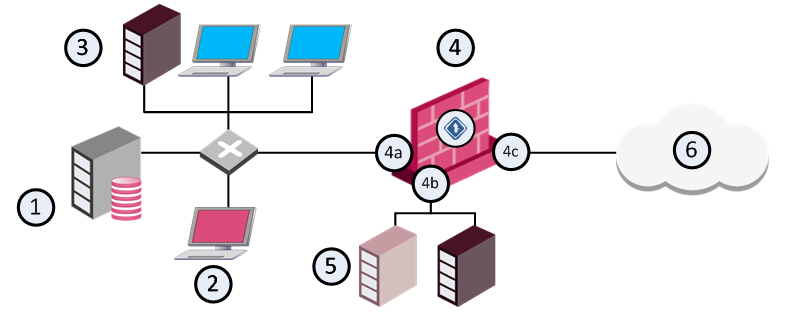
Deployment Scenario for this Tutorial
|
Item |
Description |
|---|---|
|
1 |
|
|
2 |
Cambridge - SmartConsole client |
|
3 |
Local area network - Engineering and Marketing |
|
4 |
London - Security Gateway |
|
4a |
Interface eth2 - 199.199.199.32 |
|
4b |
Interface eth1 - 199.32.43.32 |
|
4c |
Interface eth0 - 199.32.32.32 |
|
5 |
DMZ with Web and FTP servers |
|
6 |
Internet |
This scenario is an organization with offices located in London, Oxford and Cambridge. The QoS Security Gateway is in London and has three interfaces, one of which is connected to the Internet. The Security Management Server![]() Check Point Single-Domain Security Management Server or a Multi-Domain Security Management Server. is in Oxford and the SmartConsole is in Cambridge. The local network includes the Marketing and Engineering departments.
Check Point Single-Domain Security Management Server or a Multi-Domain Security Management Server. is in Oxford and the SmartConsole is in Cambridge. The local network includes the Marketing and Engineering departments.
Tutorial Workflow
This tutorial is a simplified exercise that shows you how to do these QoS activities:
-
Install and configure the system components.
-
Create a new QoS Policy with SmartConsole.
-
Select one of these QoS Policies types:
-
Express - Quickly create basic QoS Policies.
-
Recommended - Create advanced Policies with the full set of QoS features.
-
-
Configure the network objects used by QoS rules.
-
Configure specialized services for use in QoS rules.
-
Create QoS Policy rules.
-
Install the Policy on the Security Gateway.
Installing the System Components
To install and configure system components for this tutorial:
-
Enable QoS, Firewall, and other Software Blades on the London Security Gateway.
-
Install a Security Management Server on the Oxford server platform.
-
Install SmartConsole on the Cambridge PC.
-
In SmartConsole, define Cambridge as a trusted client.
-
In SmartConsole, define the administrators who can manage the QoS Policy.
-
Make sure that there is SIC
Secure Internal Communication. The Check Point proprietary mechanism with which Check Point computers that run Check Point software authenticate each other over SSL, for secure communication. This authentication is based on the certificates issued by the ICA on a Check Point Management Server. trust between the Oxford Security Management Server and the London QoS Security Gateway.
Starting SmartConsole
This section describes how to open SmartDashboard and access the QoS tab.
To Create a New QoS Policy
-
On the gateway, make sure that the QoS blade is enabled.
-
In SmartConsole, from the File menu, select Manage Policies and Layers.
-
Click New.
-
In the Policy window, enter a Policy name.
This name cannot:
-
Contain any reserved words or spaces.
-
Start with a number.
-
Contain any of the following characters:
%, #, ', &, *, !, @, ?, <, >, /, \, :. -
End with any of the following suffixes:
.pf,.W.
-
-
Select QoS and then select a QoS Policy type:
-
Express - Quickly create basic QoS Policies
-
Recommended (default) - Create advanced Policies with the full set of QoS features

Note: There are some limitations that can prevent you from enabling SecureXL
Check Point product on a Security Gateway that accelerates IPv4 and IPv6 traffic that passes through a Security Gateway. or CoreXL Performance-enhancing technology for Security Gateways on multi-core processing platforms. Multiple Check Point Firewall instances are running in parallel on multiple CPU cores. with QoS Policies. For more, see: Acceleration Support for R77 Policies . -
-
Click OK.
The system saves the new Policy and SmartDashboard opens automatically. You can start to define your rules here.
Planning the QoS Policy
To implement a good QoS Policy, find out how the network is used. Identify and prioritize the types of traffic. Identify users and their needs. For example:
-
HTTP traffic must be allocated more bandwidth than RealAudio.
-
Marketing must be allocated more bandwidth than Engineering.
Configuring the Security Gateway
Define these Network Objects:
-
London, the Security Gateway on which the QoS is enabled
-
Sub-networks for the Marketing and Engineering departments
To define the London Security Gateway:
-
In SmartConsole, click Gateways & Servers.
-
Click New > Gateway > Classic Mode.
-
Configure these parameters in the General Properties window.
Field
Value
Notes
Name
London
This is the name by which the object is known on the network; the response to the hostname command.
Platform
Select an appliance type or Open Server
The platform must be supported for R80.40
SIC
Click Communication
Establishes a secure communication channel between the Security Gateway and the management server.
Version
R80.40
OS
IP Address
192.32.32.32
This is the interface associated with the host name in the DNS - get this by clicking Get Address.
For gateways, this should always be the IP address of the external interface.
Network Security Tab
Firewall and QoS
Defining Interfaces on the Gateway
In this step you configure each interface and its QoS properties.
To configure interface properties:
-
Click Network Management in the navigation tree.
-
Click Get Interfaces on the toolbar.
The interfaces show in the Network Management window.
-
Double-click each interface and configure parameters in the Interface > General window.
eth0
Field
Value
Notes
Net Address
192.32.32.32
Net Mask
255.255.255.0
Topology Settings
(Click Modify)
Internet External
This interface connects to the Internet.
Anti-Spoofing
Perform Anti-Spoofing based on interface topology
Each incoming packet is examined to make sure that the source IP address is valid.
Spoof Tracking
Log
Log Anti-Spoofing events.
eth1
Field
Value
Notes
Net Address
192.32.42.32
Net Mask
255.255.255.0
Topology Settings
(Click Modify)
Internet External
This interface connects to the Internet.
Anti-Spoofing
Perform Anti-Spoofing based on interface topology
Each incoming packet is examined to make sure that the source IP address is valid.
Spoof Tracking
Log
Log Anti-Spoofing events.
eth2
Field
Value
Notes
Net Address
192.199.199.32
Net Mask
255.255.255.0
Topology Settings
(Click Modify)
Internet External
This interface connects to the Internet.
Anti-Spoofing
Perform Anti-Spoofing based on interface topology
Each incoming packet is examined to make sure that the source IP address is valid.
Spoof Tracking
Log
Log Anti-Spoofing events.
To Configure QoS Properties for Interfaces
-
In the Interface window, click the QoS tab.
-
Select Inbound Active and Outbound Active.
-
Set Inbound Active and Outbound Active to 192000 - T1 (1.5 Mbps).
Defining the Services
The QoS Policy required for this tutorial does not require the definition of new proprietary services. The commonly used services HTTP and RealAudio are already defined in QoS.
Creating and Configuring Rules
After you define your network objects and services, the next step is to create your QoS policy rules. This tutorial shows you how to create two simple QoS rules. A new QoS Policy always includes a Default Rule![]() Set of traffic parameters and other conditions in a Rule Base (Security Policy) that cause specified actions to be taken for a communication session. (see Default Rule ).
Set of traffic parameters and other conditions in a Rule Base (Security Policy) that cause specified actions to be taken for a communication session. (see Default Rule ).
To Create a New Policy
-
In SmartConsole select New from the File menu.
The New Policy window opens.
-
Enter the name in the New policy Package Name field.
-
Select QoS.
-
Select QoS policy (recommended).
-
Click OK.
The new Policy is created together with a Default Rule and is displayed in the QoS tab.
Creating New Rules
When you create a new QoS Policy, the system automatically adds a default rule, which must always be the last rule in the Policy. Make sure that you add your new rules above the default rule.
Create these two rules: Web Rule and RealAudio Rule.
-
In SmartDashboard > QoS tab, select the default rule.
-
Click the Before current rule icon.
-
Enter Web Rule in the Rule Name window, and then click OK.
Do this procedure again for RealAudio Rule.
Rule Properties
A new rule has the default values assigned by the administrator. The next procedure describes how to change these rules to the values shown in the table below.
Changing Rules Default Values
|
Rule Name |
Source |
Destination |
Service |
Action |
|---|---|---|---|---|
|
Web Rule |
Any |
Any |
HTTP |
Weight 35 |
|
RealAudio Rule |
Any |
Any |
RealAudio |
Weight 5 |
|
Default |
Any |
Any |
Any |
Weight 10 |
Changing New Rule Properties
The system automatically assigns the default parameters as defined in the Global Properties > QoS to new rules. Use this procedure to change these rules to the values shown in the table below.
|
Rule Name |
Source |
Destination |
Service |
Action |
|---|---|---|---|---|
|
Web Rule |
Any |
Any |
HTTP |
Weight 35 |
|
RealAudio Rule |
Any |
Any |
RealAudio |
Weight 5 |
|
Default |
Any |
Any |
Any |
Weight 10 |
To change the properties in a rule:
-
In the QoS tab, right-click in the Service field of the Web Rule.
Select Add Objects, and then select HTTP from the list.
-
Double-click the Action field, and then change the Rule Weight property to 35. For more, see: Changing QoS Global Properties
Do this procedure again for the RealAudio and Default rules.
Classifying Traffic by Service
Usually, a full Rule Base will not explicitly define rules for all the "background" services (such as DNS and ARP). Background services are handled by the Default rule.
The structure of the Rule Base is shown at the left of the window as a tree, with the Default Rule at the bottom. (For a description of the Rule Base window, see Basic Policy Management).
Connections receive bandwidth according to the weights (priority) assigned to the rules that apply to them. The table below describes what occurs when there are four active connections. Note that bandwidth allocation is constantly changing.
Service Rules - Four Active Connections
|
Connections |
Relevant rule |
Bandwidth |
Comments |
|---|---|---|---|
|
HTTP |
Web Rule |
70% |
35 / 50 (the total weights) |
|
RealAudio |
RealAudio Rule |
10% |
5 / 50 |
|
FTP |
Default |
sharing 20% |
10 /50; a rule applies to all the connections together |
|
TELNET |
Default |
sharing 20% |
10 /50; a rule applies to all the connections together |
Bandwidth is allocated between connections according to relative weight. As connections are opened and closed, QoS changes the bandwidth allocation according to the QoS Policy.
For example:
-
If the HTTP, FTP and TELNET connections are all closed. The only remaining connection is the RealAudio connection. RealAudio receives 100% of the bandwidth.
-
If the TELNET and FTP connections are closed, both HTTP and RealAudio benefit from the released bandwidth.
Service Rules - Two Active Connections
|
Connections |
Relevant rule |
Bandwidth |
Comments |
|---|---|---|---|
|
HTTP |
Web Rule |
87/5% |
35 / 40 (the total weights) |
|
RealAudio |
RealAudio Rule |
12.5% |
5 / 40 |
Although RealAudio is assigned a very small weight compared to HTTP, it will not be starved of bandwidth no matter how heavy the HTTP traffic.
In practice, you will probably want to give a high relative weight to interactive services such as TELNET, which transfers small amounts of data but involves users issuing commands.
Classifying Traffic by Source
The second part of the QoS Policy (Marketing must be allocated more bandwidth than Engineering) is implemented by these rules:
Marketing is Allocated More Bandwidth Than Engineering
|
Rule Name |
Source |
Destination |
Service |
Action |
|---|---|---|---|---|
|
Marketing Rule |
Marketing |
Any |
Any |
Weight 30 |
|
Engineering Rule |
Engineering |
Any |
Any |
Weight 20 |
|
Default |
Any |
Any |
Any |
Weight 10 |
Using the same principles described in Creating New Rules and Changing New Rule Properties, create new rules in SmartConsole and change them to match the values shown in the table above. The effect of these rules is equivalent to the rules shown here:
|
Connections |
Relevant rule |
Bandwidth |
Comments |
|---|---|---|---|
|
HTTP |
Web Rule |
70% |
35 / 50 (the total weights) |
|
RealAudio |
RealAudio Rule |
10% |
5 / 50 |
|
FTP |
Default |
sharing 20% |
10 /50 A rule applies to all the connections together |
|
TELNET |
Default |
sharing 20% |
10 /50 A rule applies to all the connections together |
Except for:
-
the different weights
-
the fact that allocation is based on source rather than on services
Classifying Traffic by Service and Source
The table below shows all the rules in one Rule Base.
All the Rules Together
|
Rule Name |
Source |
Destination |
Service |
Action |
|---|---|---|---|---|
|
Web Rule |
Any |
Any |
HTTP |
Weight 35 |
|
RealAudio Rule |
Any |
Any |
RealAudio |
Weight 5 |
|
Marketing Rule |
Marketing |
Any |
Any |
Weight 30 |
|
Engineering Rule |
Engineering |
Any |
Any |
Weight 20 |
|
Default |
Any |
Any |
Any |
Weight 10 |
In this Rule Base, bandwidth allocation is based both on sub-networks and on services.
First Rule Match Principle
In the Rule Base shown below:
|
Rule Name |
Source |
Destination |
Service |
Action |
|---|---|---|---|---|
|
Web Rule |
Any |
Any |
HTTP |
Weight 35 |
|
RealAudio Rule |
Any |
Any |
RealAudio |
Weight 5 |
|
Marketing Rule |
Marketing |
Any |
Any |
Weight 30 |
|
Engineering Rule |
Engineering |
Any |
Any |
Weight 20 |
|
Default |
Any |
Any |
Any |
Weight 10 |
In a production environment, a connection can match more than one rule. QoS works according to a first rule match principle. Each connection is examined against the QoS Policy and receives bandwidth according to the Action defined in the first rule that is matched.
If a user in Marketing initiates an HTTP connection, the connection matches the Web Rule and the Marketing Rule. The Web Rule comes before the Marketing Rule in the Rule Base, so the connection is matched to the Web Rule and given a weight of 35.
To differentiate HTTP traffic by source, create sub-rules for the Web Rule. See Sub-Rules.
Guarantees and Limits
Bandwidth allocation can also be defined using guarantees and limits. You can define guarantees and limits for rules or for individual connections in a rule.
|
Rule Name |
Source |
Destination |
Service |
Action |
|---|---|---|---|---|
|
Web Rule |
Any |
Any |
HTTP |
Weight 35 |
|
RealAudio Rule |
Any |
Any |
RealAudio |
Weight 5 |
|
Marketing Rule |
Marketing |
Any |
Any |
Weight 30 |
|
Engineering Rule |
Engineering |
Any |
Any |
Weight 20 |
|
Default |
Any |
Any |
Any |
Weight 10 |
The Web Rule shown in the Rule Base allocates 35% of available bandwidth to all the HTTP connections combined. The actual bandwidth allocated to connections that match this rule depends on:
-
Total available bandwidth
-
Open connections that match other rules
|
|
Note - 35% of available bandwidth (specified in the example above) is assured to Web Rule. Web Rule will get more bandwidth if there are fewer connections matched to other rules, but never less than 35%. |
As an alternative to relative weights, a guarantee can be used to specify bandwidth as an absolute value (in Bytes per second). In this table, Web Rule is guaranteed 20 KBps:
Guarantee Example
|
Rule Name |
Source |
Destination |
Service |
Action |
|---|---|---|---|---|
|
Web Rule |
Any |
Any |
HTTP |
Guarantee 20 KBps Weight 35 |
|
RealAudio Rule |
Any |
Any |
RealAudio |
Weight 5 |
|
Marketing Rule |
Marketing |
Any |
Any |
Weight 30 |
|
Engineering Rule |
Engineering |
Any |
Any |
Weight 20 |
|
Default |
Any |
Any |
Any |
Weight 10 |
Connections matched to Web Rule will receive a total bandwidth of 20 KBps. Remaining bandwidth will be allocated to all the rules, Web Rule included, according to their weights.
For more on guarantees and limits, see Examples: Guarantees and Limits and Bandwidth Allocation and Sub-Rules.
Sub-Rules
Sub-rules are rules nested in a rule. For example, you can create a sub-rule that allocates more bandwidth to HTTP connections that originate in Marketing. Connections whose Source is marketing receive more bandwidth than other HTTP traffic. In this example, the marketing sub-rule and default sub-rule is below the Web Rule:
Defining Sub-Rules
|
Rule Name |
Source |
Destination |
Service |
Action |
|---|---|---|---|---|
|
Web Rule |
Any |
Any |
|
Weight 20 |
|
Start of Sub-Rule |
||||
|
Marketing HTTP |
Marketing |
Any |
Any |
Weight 10 |
|
Default |
Any |
Any |
Any |
Weight 1 |
|
End of Sub-Rule |
||||
Bandwidth is allocated to Web Rule according to its weight (20). This weight is divided between its sub-rules in a 10:1 ratio. Connections below Web Rule are allocated bandwidth according to the weights specified:
-
10 for HTTP traffic from the Marketing department
-
1 for everything else.
|
|
Notes:
|
To create a sub-rule:
-
Right-click in the Name field of the rule in which you want to create the sub-rule.
-
Select Add Sub-Rule.
Installing a QoS Policy
To install a QoS Policy:
-
In SmartDashboard, make changes to Policy rules and then click Update.
-
In SmartConsole, click Install Policy.
-
From the Policy list, select the policy to install.
-
Click Policy Targets and select the Security Gateways that will get this Policy.
Note -By default, no gateways are selected for QoS. You must select them manually.
-
Click Install.
If the installation is successful, the new Policy is enforced by the Security Gateways on which it is installed. If installation fails, do these steps to see the error messages:
-
Click the Task Information area, in the lower, left hand corner of SmartConsole.
-
In the Recent Tasks area, click Details on the applicable error.
In the Install Policy Details window, click the ^ icon in the Status column to see the error messages. You must resolve all errors before you can successfully install the Policy.