ISP Redundancy on a Cluster
|
|
Important - ISP Redundancy is not supported if Dynamic Routing is configured (Known Limitation PMTR-68991). |

|
|
Note - For information about ISP Redundancy on a Security Gateway |

Introduction
ISP Redundancy lets you connect Cluster![]() Two or more Security Gateways that work together in a redundant configuration - High Availability, or Load Sharing. Members to the Internet through redundant Internet Service Provider (ISP) links.
Two or more Security Gateways that work together in a redundant configuration - High Availability, or Load Sharing. Members to the Internet through redundant Internet Service Provider (ISP) links.
ISP Redundancy monitors the ISP links and chooses the best current link.
|
|
Notes:
|
|
|
Important:
|
IP addresses in the table below are only examples.
|
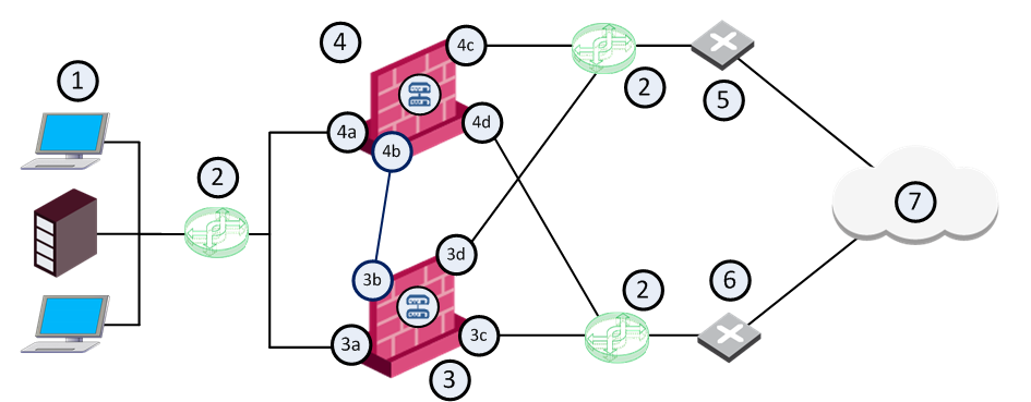
Item |
Description |
|---|---|
|
1 |
Internal network |
|
2 |
Switches |
|
3 |
Cluster Member A |
|
3a |
Cluster interface
|
|
3b |
Cluster interface (IP address 20.20.20.11) connected to the Sync network (IP address 20.20.20.0/24) |
|
3c |
Cluster interface connected to a switch that connects to ISP A
|
|
3d |
Cluster interface connected to a switch that connects to ISP B
|
|
4 |
Cluster Member B |
|
4a |
Cluster interface connected to the internal network (IP address 10.10.10.0/24)
|
|
4b |
Cluster interface (IP address 20.20.20.22) connected to the Sync network (IP address 20.20.20.0/24) |
|
4c |
Cluster interface connected to a switch that connects to ISP B
|
|
4d |
Cluster interface connected to a switch that connects to ISP A
|
|
5 |
ISP B |
|
6 |
ISP A |
|
7 |
Internet |
ISP Redundancy Modes
ISP Redundancy configuration modes control the behavior of outgoing connections from internal clients to the Internet:
|
Mode |
Description |
|---|---|
|
Uses the two links to distribute load of connections. Connections coming in are alternated. You can configure best relative loads for the links (set a faster link to handle more load). New connections are randomly assigned to a link. If one link fails, the other link takes the load. In this mode, incoming connections can reach the application servers through either ISP link because the |
|
|
Primary/Backup |
Uses one link for connections. It switches to the Backup When the Primary link is restored, new connections are assigned to it. Existing connections continue on the Backup link until they are complete. In this mode, incoming connections (from the Internet to application servers in the DMZ or internal networks) also benefit, because the |
|
|
Best Practice:
|

Outgoing Connections
-
In ISP Redundancy Load Sharing mode, outgoing traffic that exits the
For example, if one link is faster, it can be configured to route more traffic across that ISP link than the other.
-
In ISP Redundancy Primary/Backup mode, outgoing traffic uses an active
 State of a Cluster Member that is fully operational: (1) In ClusterXL, this applies to the state of the Security Gateway component (2) In 3rd-party / OPSEC cluster, this applies to the state of the cluster State Synchronization mechanism. primary link.
Hide NAT is used to change the source address of outgoing packets to the address of the interface, through which the packet leaves the
Incoming Connections
For external users to make incoming connections, the administrator must give each application server two routable IP addresses, one for each ISP. The administrator must also configure Static NAT to translate the routable addresses to the real server address.
If the servers handle different services (for example, HTTP and FTP), you can use NAT to employ only two routable IP addresses for all the publicly available servers.
External clients use one of the two addresses. In order to connect, the clients must be able to resolve the DNS name of the server to the correct IP address.
|
|
Note - In the following example, the subnets 172.16.0.0/24 and 192.168.0.0/24 represent public routable addresses. |
In the following example, the Web server www.example.com is assigned an IP address from each ISP:
-
192.168.1.2 from ISP A
-
172.16.2.2 from ISP B
If the ISP Link A is down![]() State of a Cluster Member during a failure when one of the Critical Devices reports its state as "problem": In ClusterXL, applies to the state of the Security Gateway component; in 3rd-party / OPSEC cluster, applies to the state of the State Synchronization mechanism. A Cluster Member in this state does not process any traffic passing through cluster., then IP address 192.168.1.2 becomes unavailable, and the clients must be able to resolve the URL www.example.com to the IP address 172.16.2.2.
State of a Cluster Member during a failure when one of the Critical Devices reports its state as "problem": In ClusterXL, applies to the state of the Security Gateway component; in 3rd-party / OPSEC cluster, applies to the state of the State Synchronization mechanism. A Cluster Member in this state does not process any traffic passing through cluster., then IP address 192.168.1.2 becomes unavailable, and the clients must be able to resolve the URL www.example.com to the IP address 172.16.2.2.
An incoming connection is established, based on this example, in the following sequence:
-
When an external client on the Internet contacts www.example.com, the client sends a DNS query for the IP address of this URL.
The DNS query reaches the
-
A DNS query arriving at an interface that belongs to one of the ISP links, is intercepted by the
-
If the
-
In ISP Redundancy Primary/Backup mode, the
-
In ISP Redundancy Load Sharing mode, the
-
-
If the
-
When the external client receives the reply to its DNS query, it opens a connection. Once the packets reach the
-
The