


|
|
|
Important - Virtual Switches are not supported (see Known Limitation MBS-5214).
Virtual Switches provide level-2 connectivity between Virtual Systems and internal or external networks. This section describes how to define and configure a Virtual Switch. As with physical switches, each Virtual Switch maintains a forwarding table containing entries that describe known networks and directions for reaching them.
You can define Virtual Switches for external and internal communications.
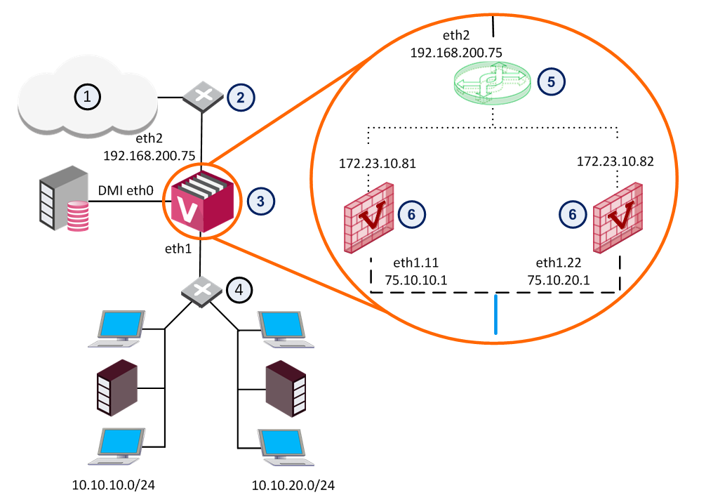
Item |
Description |
|
Item |
Description |
|---|---|---|---|---|
1 |
Internet |
|
6 |
Virtual Systems |
2 |
Router |
|
|
VLAN Interface |
3 |
VSX Gateway |
|
|
VLAN Trunk |
4 |
VLAN Switch |
|
|
Warp Link |
5 |
Virtual Switch |
|
|
|
The figure shows a typical deployment using a Virtual Switch for external connections and a VLAN trunk leading to the internal, protected network.
The General Properties page allows you to add comments and change the icon color as displayed in SmartConsole.
The Topology page defines Virtual Switch interfaces. You can only modify the single defined interface. You cannot change the settings for Warp interfaces in this window.
To add an interface:
The Interface Properties window opens.
When you delete a VSX Gateway object, the operation automatically deletes all Virtual Systems and other Virtual Devices associated with that VSX Gateway from the management database.
To delete a VSX Gateway:

