


|
|
|
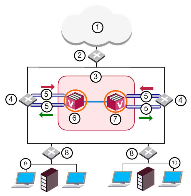
Many Enterprise environments are based on core networks. Situated adjacent to core network backbone switches, VSX protects the internal network by providing security at layer-2, layer-3 or both. VSX communicates with the core network using the existing infrastructure. With Virtual Systems in the Bridge Mode, VSX can protect departmental networks, while simultaneously preventing network segmentation. In this case, switches are located at the entrance to each department's network.
Item |
Description |
|
Item |
Description |
|---|---|---|---|---|
1 |
Internet |
|
8 |
LAN Switches |
2 |
Core Network Backbone switch |
|
9 |
Sales |
3 |
VSX Cluster |
|
10 |
Finance |
4 |
Router |
|
|
Sync Network |
5 |
VLAN |
|
|
Physical Interface |
6 |
Member 1 |
|
|
VLAN Trunk |
7 |
Member 2 |
|
|
|
VSX ensures connectivity between the core network and the Internet or external networks, while providing perimeter security. Security can be configured on a per VLAN basis.
A three-layer hierarchical model is used in large, high-traffic network environments.
VSX in Active/Standby Bridge Mode is incorporated in the distribution layer, enforcing the security policy.
The routers direct external traffic to the appropriate Virtual System through a segregated VLAN. Inspected traffic exits the Virtual System through a separate segregated VLAN, to the routers and then to internal destinations.
To configure a Virtual System in Bridge Mode, define it as such when you first create the Virtual System object.
To configure a Virtual System for the Active/Standby Bridge Mode:
The Virtual System Network Configuration window opens.
The IP address must be unique and on the same subnet as the protected network.
cpconfigEnter y and continue with the gateway configuration.
cpconfigcpconfigIf you used the Custom Configuration template to create the VSX Gateway, or if you selected the Override Creation Template option for a Virtual System in Bridge Mode, then manually define the network interfaces.
Interfaces: To configure the external and internal interfaces, define interfaces and links to devices in the Interfaces table. You can add, change, and remove interfaces. To add an interface, click Add. The Interface Properties window opens. Select an interface from the list and define is properties.
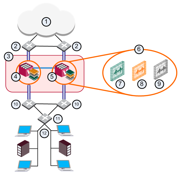
In this deployment, each member connects to pair of redundant switches through a VLAN Trunk. All Virtual Systems in a given VSX Cluster Member share the same VLAN Trunk.
Item |
Description |
|
Item |
Description |
|---|---|---|---|---|
1 |
Internet |
|
9 |
Virtual System 3 is Backup |
2 |
Redundant switches (external) |
|
10 |
Redundant switches (internal) |
3 |
VSX Cluster |
|
11 |
VLAN Switch |
4 |
VSX Cluster Member 1 |
|
12 |
Internal Networks |
5 |
VSX Cluster Member 2 |
|
|
Sync Network |
6 |
Virtual Systems in Bridge Mode |
|
|
Physical Interface |
7 |
Virtual System 1 is Active |
|
|
VLAN Trunk |
8 |
Virtual System 2 is Standby |
|
|
|
With Active/Standby Bridge Mode in High Availability mode, VSX Cluster directs traffic to VSX Cluster Members according to administrator-defined priorities and status.
In Virtual System Load Sharing deployments, the system distributes the traffic load amongst VSX Cluster Members according to the Virtual System Load Sharing configuration.
A VSX Cluster has two or more identical, interconnected VSX Gateways for continuous data synchronization and transparent failover. Virtual System Load Sharing (VSLS) enhances throughput by distributing Virtual Systems, with their traffic load, among multiple, redundant machines.
To enable the Active/Standby Bridge Mode for a cluster:
The VSX Cluster Properties window opens.
The Active/Standby Bridge Mode loop detection algorithms in ClusterXL are enabled.
To enable the Active/Active Bridge mode for a cluster:
The VSX Cluster Properties window opens.
The Virtual System Network Configuration page for the Separate Interfaces template in the Bridge Mode opens.
To configure the external and internal interfaces:
If the selected Interface is a VLAN interface, enter the same VLAN tag in both the external and internal VLAN Tag fields. This field is not available for non-VLAN interfaces.
Enter an IP address and subnet mask, which continuously monitors the specified network for faults or connectivity issues. The IP address/Subnet Mask define the network, on which the Virtual System resides.
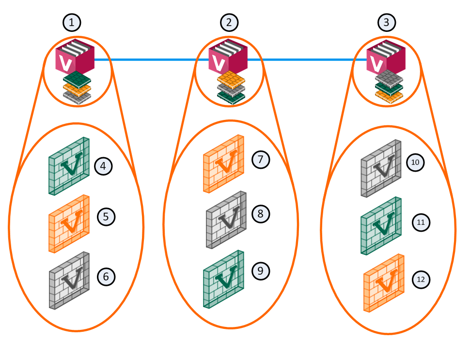
VSX Clusters can efficiently balance network traffic load by distributing active Virtual Systems amongst VSX Cluster Members. This capability is known as Virtual System Load Sharing (VSLS).
In a deployment scenario with three VSX Cluster Members, each with three Virtual Systems: an equalized Load Sharing deployment might have one Active Virtual System on each VSX Cluster Member.
Item |
Description |
|
Item |
Description |
|---|---|---|---|---|
1 |
VSX Cluster Member 1 |
|
8 |
Virtual System 2 is Backup |
2 |
VSX Cluster Member 2 |
|
9 |
Virtual System 3 is Active |
3 |
VSX Cluster Member 3 |
|
10 |
Virtual System 1 is Backup |
4 |
Virtual System 1 is Active |
|
11 |
Virtual System 2 is Active |
5 |
Virtual System 2 is Standby |
|
12 |
Virtual System 3 is Standby |
6 |
Virtual System 3 is Backup |
|
|
Sync Network |
7 |
Virtual System 1 is Standby |
|
|
|
A different member hosts the active peer for each Virtual System. This distribution spreads the load equally amongst the VSX Cluster Members. When you create a Virtual System, VSX automatically assigns Standby and Backup states to the appropriate peers and distributes them among the other VSX Cluster Members.
In the event that a VSX Cluster Member fails, VSLS directs traffic destined to affected Virtual Systems to their fully synchronized Standby peers, which then become Active. At the same time, a Backup Virtual System switches to Standby, and synchronizes with the newly Active Virtual System.
In the event that an individual active Virtual System fails, it immediately fails over to its Standby peer and one of its Backup peers becomes the Standby, synchronizing with the newly Active peer.
To convert an existing VSX Cluster from High Availability to VSLS:
cpconfig
cpstop ; cpstart
vsx_util convert_cluster
LS
Proceed with conversion? prompt, enter: yvsx state -v
cphaprob state
Note - You cannot convert a VSX Cluster to the VSLS mode, if it contains Virtual Systems in the Active/Active Bridge mode or Virtual Routers.

