


|
|
|
Note - This procedure applies to both Check Point Appliances and Open Servers.
Item |
Description |
|---|---|
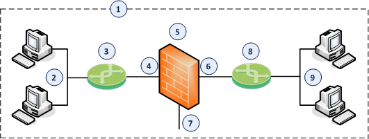
1 |
Network, which an administrator needs to divide into two Layer 2 segments. The Security Gateway in Bridge Mode connects between these segments. |
2 |
First network segment. |
3 |
Switch that connects the first network segment to one bridged slave interface (4) on the Security Gateway in Bridge Mode. |
4 |
One bridged slave interface (for example, |
5 |
Security Gateway in Bridge Mode. |
6 |
Another bridged slave interface (for example, |
7 |
Dedicated Gaia Management Interface (for example, |
8 |
Switch that connects the second network segment to the other bridged slave interface (6) on the Security Gateway in Bridge Mode. |
9 |
Second network segment. |
Workflow:
Step 1 of 4: Install the Security Gateway
Step |
Description |
|---|---|
1 |
Install the Gaia Operating System: |
2 |
|
3 |
During the First Time Configuration Wizard, you must configure these settings:
|
Step 2 of 4: Configure the Bridge interface in Gaia Portal:
Step |
Description |
|---|---|
1 |
In your web browser, connect to the Gaia Portal on the Security Gateway. |
2 |
In the left navigation tree, click Network Management > Network Interfaces. |
3 |
Make sure that the interfaces, which you wish to add as slaves of the Bridge interface, do not have IP addresses assigned to them. |
4 |
Click Add > Bridge. To configure an existing Bridge interface, select the Bridge interface and click Edit. |
5 |
On the Bridge tab, enter or select a Bridge Group ID (unique integer between 1 and 1024). |
6 |
Select the interfaces from the Available Interfaces list and then click Add. Notes:
|
7 |
On the IPv4 tab, enter the IPv4 address and subnet mask. |
8 |
On the IPv6 tab (optional), enter the IPv6 address and mask length. Important - First, you must enable the IPv6 Support in Gaia and reboot. |
9 |
Click OK. |
Step 2 of 4: Configure the Bridge interface in Gaia Clish:
Step |
Description |
|---|---|
1 |
Connect to the command line on the Security Gateway. |
2 |
Log in to Gaia Clish. |
3 |
Make sure that the interfaces, which you wish to add as slaves of the Bridge interface, do not have IP addresses assigned to them. Run:
|
4 |
Add a new bridging group. Run:
|
5 |
Add the slave interfaces to the new bridging group:
|
6 |
Assign an IP address to the bridging group. To assign an IPv4 address, run:
To assign an IPv6 address, run:
|
7 |
Save the configuration. Run:
|
Step 3 of 4: Configure the Security Gateway object in SmartConsole - Wizard Mode
Step |
Description |
|---|---|
1 |
Connect with SmartConsole to the Security Management Server or Domain Management Server that should manage this Security Gateway. |
2 |
From the left navigation panel, click Gateways & Servers. |
3 |
Create a new Security Gateway object in one of these ways:
|
4 |
In the Check Point Security Gateway Creation window, click Wizard Mode. |
5 |
On the General Properties page:
|
6 |
On the Trusted Communication page:
|
7 |
On the End page:
Check Point Gateway properties window opens on the General Properties page. |
8 |
If during the Wizard Mode, you selected Skip and initiate trusted communication later:
|
9 |
On the Network Security tab, enable the additional desired Software Blades. Important:
|
10 |
On the Network Management page, configure the Topology of the Bridge interface. Notes:
|
11 |
Click OK. |
12 |
Publish the SmartConsole session. |
Step 3 of 4: Configure the Security Gateway object in SmartConsole - Classic Mode
Step |
Description |
|---|---|
1 |
Connect with SmartConsole to the Security Management Server or Domain Management Server that should manage this Security Gateway. |
2 |
From the left navigation panel, click Gateways & Servers. |
3 |
Create a new Security Gateway object in one of these ways:
|
4 |
In the Check Point Security Gateway Creation window, click Classic Mode. Check Point Gateway properties window opens on the General Properties page. |
5 |
In the Name field, enter the desired name for this Security Gateway object. |
6 |
In the IPv4 address and IPv6 address fields, configure the same IPv4 and IPv6 addresses that you configured on the Management Connection page of the Security Gateway's First Time Configuration Wizard. Make sure the Security Management Server or Multi-Domain Server can connect to these IP addresses. |
7 |
Establish the Secure Internal Communication (SIC) between the Management Server and this Security Gateway:
|
|
If the Certificate state field does not show
|
8 |
In the Platform section, select the correct options:
|
9 |
On the Network Security tab, enable the additional desired Software Blades. Important:
|
10 |
On the Network Management page, configure the Topology of the Bridge interface. Notes:
|
11 |
Click OK. |
12 |
Publish the SmartConsole session. |
Step 4 of 4: Configure the applicable policy for the Security Gateway in SmartConsole
Step |
Description |
|---|---|
1 |
Connect with SmartConsole to the Security Management Server or Domain Management Server that manages this Security Gateway. |
2 |
From the left navigation panel, click Security Policies. |
3 |
Create a new policy and configure the applicable layers:
|
4 |
Create the applicable Access Control rules. Important - See the Supported Software Blades in Bridge Mode and Limitations in Bridge Mode. |
5 |
Install the Access Control Policy on the Security Gateway object. |
For more information, see the:

