VSX Routing Concepts
|
|
Important:
|

Routing Overview
The traffic routing features in VSX![]() Virtual System Extension. Check Point virtual networking solution, hosted on a computer or cluster with virtual abstractions of Check Point Security Gateways and other network devices. These Virtual Devices provide the same functionality as their physical counterparts. network topologies are analogous to those available for physical networks. This section discusses several routing features and strategies as they apply to a VSX environment.
Virtual System Extension. Check Point virtual networking solution, hosted on a computer or cluster with virtual abstractions of Check Point Security Gateways and other network devices. These Virtual Devices provide the same functionality as their physical counterparts. network topologies are analogous to those available for physical networks. This section discusses several routing features and strategies as they apply to a VSX environment.
Routing Between Virtual Systems
Virtual Routers and Virtual Switches can be used to send traffic between networks located behind Virtual Systems, much in the same way as their physical counterparts.
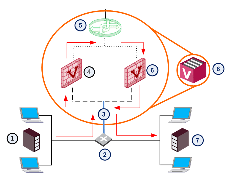
The figure below shows an example of how Virtual Systems, connected to a Virtual Switch![]() Virtual Device on a VSX Gateway or VSX Cluster Member that functions as a physical switch. Acronym: VSW. and a physical VLAN switch, communicate with each other. In this example, a host in VLAN 100 sends data to a server located in VLAN 200.
Virtual Device on a VSX Gateway or VSX Cluster Member that functions as a physical switch. Acronym: VSW. and a physical VLAN switch, communicate with each other. In this example, a host in VLAN 100 sends data to a server located in VLAN 200.
|
Item |
Description |
|
Item |
Description |
|---|---|---|---|---|
|
1 |
VLAN 100 |
|
7 |
VLAN 200 |
|
2 |
VLAN Switch |
|
8 |
|
|
3 |
VLAN Trunk |
|
|
VLAN Interface |
|
4 |
|
|
VLAN Trunk |
|
|
5 |
Virtual Switch |
|
|
|
|
6 |
Virtual System 2 |
|
|
|


-
Traffic from the VLAN 100 host arrives at the VLAN switch, which inserts a VLAN tag and sends it to the VSX Gateway by way of a VLAN trunk.
-
Based on its VLAN tag, the VSX Gateway assigns the traffic to the Virtual System named VS1.
-
VS1 inspects the traffic according to its security policy
 Collection of rules that control network traffic and enforce organization guidelines for data protection and access to resources with packet inspection. and sends the traffic on to the Virtual Switch. Based on its routing configuration, VS1 sends the traffic to VS2 by way of the Virtual Switch.
 -
VS2 inspects the traffic according to its security policy, inserts a VLAN tag, and sends it to back the VLAN switch.
-
The VLAN switch sends the traffic to the server located on VLAN 200.
Route Propagation
When a Virtual System is connected to a Virtual Router![]() Virtual Device on a VSX Gateway or VSX Cluster Member that functions as a physical router. Acronym: VR. or to a Virtual Switch, you can choose to propagate its static routes to adjacent Virtual Devices.
Virtual Device on a VSX Gateway or VSX Cluster Member that functions as a physical router. Acronym: VR. or to a Virtual Switch, you can choose to propagate its static routes to adjacent Virtual Devices.
This feature enables network nodes located behind neighboring Virtual Systems to communicate without the need for manual configuration of static routes.
Route propagation works by automatically updating Virtual Device![]() Logical object that emulates the functionality of a type of physical network object. Virtual Device can be on of these: Virtual Router, Virtual System, or Virtual Switch. routing tables with static routes that lead to the corresponding Virtual Systems.
Logical object that emulates the functionality of a type of physical network object. Virtual Device can be on of these: Virtual Router, Virtual System, or Virtual Switch. routing tables with static routes that lead to the corresponding Virtual Systems.
|
|
Note - Route Propagation supports only static routes that you configure in SmartConsole To use dynamic routes, must configure the required dynamic settings in each required Virtual System on the VSX Gateway / each VSX Cluster Member |

When a Virtual System is connected to a Virtual Router or to a Virtual Switch, you can choose to propagate its routing information to adjacent Virtual Devices. This feature enables network nodes located behind neighboring Virtual Systems to communicate without the need for manual configuration.
Route propagation works by automatically updating Virtual Device routing tables with routes leading to the appropriate Virtual Systems.
Route Propagation using a Virtual Router
Important - Virtual Routers are not supported (see Known Limitation 01413513).
When Virtual Systems are connected to a Virtual Router, VSX propagates routes by automatically adding entries to the routing table contained in the Virtual Router. Each entry contains a route pointing to the destination subnet using the Virtual System router-side Warp Interface (wrpj) as the next hop.
Route Propagation using a Virtual Switch
When Virtual Systems are connected to a Virtual Switch, VSX propagates routes by automatically adding entries to the routing table in each Virtual System. Each entry contains a route pointing to the destination subnet using the Virtual System Warp Interface (wrp) IP address.
Overlapping IP Address Space
VSX facilitates connectivity when multiple network segments share the same IP address range (IP address space). This scenario occurs when one VSX Gateway protects several independent networks that assign IP addresses to endpoints from the same pool of IP addresses. Thus, it is feasible that more than one endpoint in a VSX environment will have the identical IP address, provided that each is located behind different Virtual System.
Overlapping IP address space in VSX environments is possible because each Virtual System maintains its own unique state and routing tables. These tables can contain identical entries, but within different, segregated contexts. Virtual Systems use NAT to facilitate mapping internal IP addresses to one or more external IP addresses.
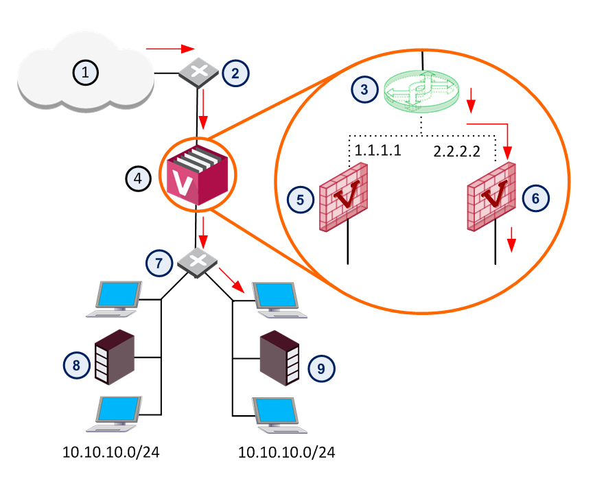
The below figure demonstrates how traffic passes from the Internet to an internal network with overlapping IP address ranges, using NAT at each Virtual System.
|
Item |
Description |
|
Item |
Description |
|---|---|---|---|---|
|
1 |
Internet |
|
6 |
Virtual System 2 |
|
2 |
Router |
|
7 |
Switch |
|
3 |
Virtual Switch |
|
8 |
Network 1 |
|
4 |
VSX Gateway |
|
9 |
Network 2 |
|
5 |
Virtual System 1 |
|
|
Warp Link |
In this case, Network 1 and Network 2 share the same network address pool, which might result in identical overlapping IP addresses. To prevent this, packets originating from or targeted to these networks are processed by their respective Virtual System using NAT to translate the original/overlapping addresses to unique routable addresses.
More for Virtual Switch Route Propagation
You are not required to manually define the topology, because this is done automatically. But there are required manual steps in the VSX objects.
To update the topology map for each Virtual System after you enable route propagation:
-
For each Virtual System object that is connected to the Virtual Switch:
-
Edit the object properties. Make sure Anti-Spoofing and VPN features are set correctly.
-
Save the object.
-
-
Install the security policy for the affected Virtual Systems.
Source-Based Routing
Source-based routing allows you to create routing definitions that take precedence over ordinary, destination-based, routing decisions. This lets you route packets according to their source IP address or a combination of their source IP address and destination IP address.
Source-based routing is useful in deployments where one physical interface without VLAN tagging connects several protected Domain networks. All Virtual Systems are connected to an internal Virtual Router. The Virtual Router sends traffic to the applicable Virtual System based on the source IP address, as defined in source-based routing rules.
Limitations
-
Source-based routing does not support overlapping IP addresses.
-
Anti-Spoofing protection is not effective for packets that originate from a shared internal interface, because there is no physical or logical segregation of traffic. In this case, it is recommended that you configure Anti-Spoofing protection on the router itself.
NAT
Virtual Systems support Network Address Translation (NAT), much in the same manner as a physical firewall. When a Virtual System, using either Static or Hide NAT, connects to a Virtual Router, you must propagate the affected routes to the Virtual Router. To do so, define NAT addresses for Virtual Systems connected to a Virtual Router.
The Virtual System - NAT > Advanced presents the configuration procedure for NAT on Virtual Machines.
Dynamic Routing
The Virtual Devices can communicate and distribute routes using dynamic routing. Each Virtual Device has its own routing daemon.
Virtual Systems support:
-
OSPF
-
RIP
-
BGP
-
PIM
Virtual Routers support:
Important - Virtual Routers are not supported (see Known Limitation 01413513).
-
OSPF