Virtual System in Bridge Mode
Core Network Security
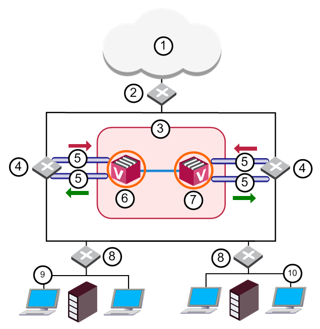
Many Enterprise environments are based on core networks. Situated adjacent to core network backbone switches, VSX![]() Virtual System Extension. Check Point virtual networking solution, hosted on a computer or cluster with virtual abstractions of Check Point Security Gateways and other network devices. These Virtual Devices provide the same functionality as their physical counterparts. protects the internal network by providing security at Layer-2, Layer-3 or both. VSX communicates with the core network using the existing infrastructure. With Virtual Systems in the Bridge Mode
Virtual System Extension. Check Point virtual networking solution, hosted on a computer or cluster with virtual abstractions of Check Point Security Gateways and other network devices. These Virtual Devices provide the same functionality as their physical counterparts. protects the internal network by providing security at Layer-2, Layer-3 or both. VSX communicates with the core network using the existing infrastructure. With Virtual Systems in the Bridge Mode![]() Security Gateway or Virtual System that works as a Layer 2 bridge device for easy deployment in an existing topology., VSX can protect departmental networks, while simultaneously preventing network segmentation. In this case, switches are located at the entrance to each department's network.
Security Gateway or Virtual System that works as a Layer 2 bridge device for easy deployment in an existing topology., VSX can protect departmental networks, while simultaneously preventing network segmentation. In this case, switches are located at the entrance to each department's network.
|
Item |
Description |
|
Item |
Description |
|---|---|---|---|---|
|
1 |
Internet |
|
8 |
LAN Switches |
|
2 |
Core Network Backbone switch |
|
9 |
Sales |
|
3 |
|
10 |
Finance |
|
|
4 |
Router |
|
|
Sync Network |
|
5 |
VLAN |
|
|
Physical Interface |
|
6 |
Member 1 |
|
|
VLAN Trunk |
|
7 |
Member 2 |
|
|
|


VSX ensures connectivity between the core network and the Internet or external networks, while providing perimeter security. Security can be configured on a per VLAN basis.
Three Layer Hierarchical Model
A three-layer hierarchical model is used in large, high-traffic network environments.
-
A core network, with high-speed backbone switches that direct traffic to and from the Internet and other external networks.
-
A distribution layer, with routers, for connectivity between the core and the access layer.
-
An access layer, with redundant LAN switches, that forward traffic to and from internal networks.
VSX in Active/Standby Bridge Mode is incorporated in the distributionlayer, enforcing the security policy![]() Collection of rules that control network traffic and enforce organization guidelines for data protection and access to resources with packet inspection..
Collection of rules that control network traffic and enforce organization guidelines for data protection and access to resources with packet inspection..
The routers direct external traffic to the appropriate Virtual System![]() Virtual Device on a VSX Gateway or VSX Cluster Member that implements the functionality of a Security Gateway. Acronym: VS. through a segregated VLAN. Inspected traffic exits the Virtual System through a separate segregated VLAN, to the routers and then to internal destinations.
Virtual Device on a VSX Gateway or VSX Cluster Member that implements the functionality of a Security Gateway. Acronym: VS. through a segregated VLAN. Inspected traffic exits the Virtual System through a separate segregated VLAN, to the routers and then to internal destinations.
Configuring Virtual Systems for Active/Standby Bridge Mode
To configure a Virtual System in Bridge Mode, define it as such when you first create the Virtual System object.
To configure a Virtual System for the Active/Standby Bridge Mode:
-
In the Virtual System General Properties page of the new Virtual System object, select Bridge Mode.
-
Click Next.
The Virtual System Network Configurationwindow opens.
-
Configure the external and internal interfaces for the Virtual System.
-
Optional: Select Enable Layer-3 Bridge Interface Monitoring.
The IP address must be unique and on the same subnet as the protected network.
-
Click Next.
-
Click Finish.
Enabling Active/Standby Bridge Mode for a New VSX Cluster Member
-
In the Gaia
 Check Point security operating system that combines the strengths of both SecurePlatform and IPSO operating systems. First Time Configuration Wizard Products page, select ClusterXL.
 -
After the First Time Configuration Wizard is complete, from the VSX Gateway
Physical server that hosts VSX virtual networks, including all Virtual Devices that provide the functionality of physical network devices. It holds at least one Virtual System, which is called VS0. CLI, run:cpconfig-
If you enabled the Per Virtual System State feature (required for VSLS), the Active/Standby Bridge Mode is enabled automatically.

Important - R80.20SP does not support VSLS (Known Limitation MBS-5288).
-
If you chose not to enable the Virtual System Load Sharing
VSX Cluster technology that assigns Virtual System traffic to different Active Cluster Members. Acronym: VSLS., an option to enable Active/Standby Bridge Mode appears.Enter
yand continue with the gateway configuration.
-
Enabling Active/Standby Bridge Mode for Existing Cluster Members
-
Connect to the command line on each VSX Cluster Member
Security Gateway that is part of a cluster.. -
Log in to the Expert mode.
-
Run:
cpconfig -
Select Enable ClusterXL for Bridge Active/Standby.
-
Reboot each VSX Cluster Member.
Enabling Active/Active Bridge Mode for Existing VSX Cluster Members
-
Connect to the command line on each VSX Cluster Member.
-
Log in to the Expert mode.
-
Run:
cpconfig -
Select Enable ClusterXL membership for this member.
-
Select Disable ClusterXL for Bridge Active/Standby.
-
Reboot each VSX Cluster Member.
Custom Configuration or Override in Bridge Mode
If you used the Custom Configuration template to create the VSX Gateway, or if you selected the Override Creation Template option for a Virtual System in Bridge Mode, then manually define the network interfaces.
Interfaces: To configure the external and internal interfaces, define interfaces and links to devices in the Interfaces table. You can add, change, and remove interfaces. To add an interface, click Add. The Interface Properties window opens. Select an interface from the list and define is properties.
VLAN Shared Interface Deployment
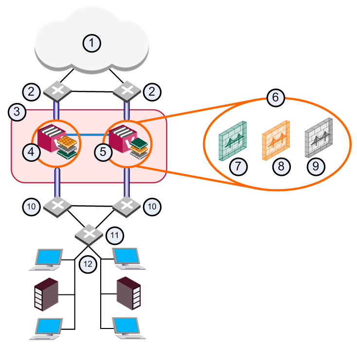
In this deployment, each member connects to pair of redundant switches through a VLAN Trunk. All Virtual Systems in a given VSX Cluster Member share the same VLAN Trunk.
|
Item |
Description |
|
Item |
Description |
|---|---|---|---|---|
|
1 |
Internet |
|
9 |
Virtual System 3 is Backup |
|
2 |
Redundant switches (external) |
|
10 |
Redundant switches (internal) |
|
3 |
VSX Cluster |
|
11 |
VLAN Switch |
|
4 |
VSX Cluster Member 1 |
|
12 |
Internal Networks |
|
5 |
VSX Cluster Member 2 |
|
|
Sync Network |
|
6 |
Virtual Systems in Bridge Mode |
|
|
Physical Interface |
|
7 |
Virtual System 1 is Active |
|
|
VLAN Trunk |
|
8 |
Virtual System 2 is Standby |
|
|
|
With Active/Standby Bridge Mode in High Availability mode, VSX Cluster directs traffic to VSX Cluster Members according to administrator-defined priorities and status.
In Virtual System Load Sharing deployments, the system distributes the traffic load amongst VSX Cluster Members according to the Virtual System Load Sharing configuration.
VSX Clusters
A VSX Cluster has two or more identical, interconnected VSX Gateways for continuous data synchronization and transparent failover. Virtual System Load Sharing (VSLS) enhances throughput by distributing Virtual Systems, with their traffic load, among multiple, redundant machines.
Configuring Clusters for Active/Standby Bridge Mode
To enable the Active/Standby Bridge Mode for a cluster:
-
Connect with SmartConsole
Check Point GUI application used to manage a Check Point environment - configure Security Policies, configure devices, monitor products and events, install updates, and so on. to the Security Management Server Dedicated Check Point server that runs Check Point software to manage the objects and policies in a Check Point environment within a single management Domain. Synonym: Single-Domain Security Management Server. or Main Domain Management Server Check Point Single-Domain Security Management Server or a Multi-Domain Security Management Server. used to manage the VSX Cluster. -
From the Gateways & Servers view or Object Explorer, double-click the VSX Cluster object.
The VSX Cluster Properties window opens.
-
From the left tree, click Other > VSX Bridge Configuration.
-
Select Check Point ClusterXL.
The Active/Standby Bridge Mode loop detection algorithms in ClusterXL are enabled.
-
Click OK.
-
Install the VSX Policy (<Name of VSX Cluster Object>_VSX) on the VSX Cluster object.
Configuring Clusters for Active/Active Bridge Mode
To enable the Active/Active Bridge mode for a cluster:
-
Connect with SmartConsole to the Security Management Server or Main Domain Management Server used to manage the VSX Cluster.
-
From the Gateways & Servers view or Object Explorer, double-click the VSX Cluster object.
The VSX Cluster Properties window opens.
-
From the left tree, click Other > VSX Bridge Configuration.
-
Select Standard Layer-2 Loop Detection Protocols.
-
Click OK.
-
Install the VSX Policy (<Name of VSX Cluster Object>_VSX) on the VSX Cluster object.
Separate Interfaces in Bridge Mode
The Virtual System Network Configuration page for the Separate Interfaces template in the Bridge Mode opens.
To configure the external and internal interfaces:
-
Select the desired interfaces for the internal and external networks from the appropriate list.
If the selected Interface is a VLAN interface, enter the same VLAN tag in both the external and internal VLAN Tag fields. This field is not available for non-VLAN interfaces.
-
Define the topology for the internal interface:
-
Select Not Defined if you do not wish to define an IP address.
-
Select Specific and then select an IP address definition from the list. IP address definitions can be based on object groups or predefined networks that define the topology.
-
-
To create a new IP address definition:
-
Select Specific, and click New.
-
Select Group to define an object group, or Network to define network properties.
-
-
Enable Layer-3 bridge interface monitoring to enable Layer 3 network fault detection for this Virtual System.
Enter an IP address and subnet mask, which continuously monitors the specified network for faults or connectivity issues. The IP address/Subnet Mask define the network, on which the Virtual System resides.