Virtual System Load Sharing (VSLS)
Virtual System Load Sharing![]() VSX Cluster technology that assigns Virtual System traffic to different Active Cluster Members. Acronym: VSLS. is a cluster
VSX Cluster technology that assigns Virtual System traffic to different Active Cluster Members. Acronym: VSLS. is a cluster![]() Two or more Security Gateways that work together in a redundant configuration - High Availability, or Load Sharing. technology that assigns traffic for Virtual Systems to different Active VSX
Two or more Security Gateways that work together in a redundant configuration - High Availability, or Load Sharing. technology that assigns traffic for Virtual Systems to different Active VSX![]() Virtual System Extension. Check Point virtual networking solution, hosted on a computer or cluster with virtual abstractions of Check Point Security Gateways and other network devices. These Virtual Devices provide the same functionality as their physical counterparts. Cluster Members, which has these benefits:
Virtual System Extension. Check Point virtual networking solution, hosted on a computer or cluster with virtual abstractions of Check Point Security Gateways and other network devices. These Virtual Devices provide the same functionality as their physical counterparts. Cluster Members, which has these benefits:
-
Capacity: VSLS leverages the cluster machines to handle greater network volume by efficiently dividing the load.
-
Redundancy: VSLS gives full redundancy by maintaining connectivity for all Virtual Systems even when individual VSX Cluster Members fail.
-
Scalability:VSLS provides linear scalability for throughput and session rate.
-
Cost Effectiveness: A VSLS cluster uses standard network switches to achieve cost effective Load Sharing.
-
Ease of Configuration: Virtual Systems are automatically distributed among all the VSX Cluster Members - no special configuration is required.
-
Priority Designation: Mission-critical Virtual Systems can be separated from the other Virtual Systems, providing advantages in terms of bandwidth and resources.
-
System Scalability: Every VSX Cluster Member
 Security Gateway that is part of a cluster. added to the cluster increases the overall system capacity and redundancy.
|
|
Note - These Virtual Devices are not supported when the Per Virtual System - Virtual Routers - Virtual Switches without physical or VLAN interfaces |

Requirements
All Virtual Systems in all VSX Cluster Members must have direct connectivity with each other. Connectivity must be accomplished using switches or VLAN connections. This is required for detecting and assigning Virtual System states.
Note - VSLS does not support Virtual Routers.
Conceptual Overview
This section presents a detailed conceptual overview of Virtual System Load Sharing.
Introduction
Virtual System Load Sharing is a cluster technology that assigns traffic for Virtual Systems to different Active VSX Cluster Members. This methodology is different from physical cluster load sharing, because it is not connection-based. Virtual System Load Sharing is useful for mission-critical deployments, where reserving bandwidth for a particular Virtual System is a priority.
VSLS lets administrators manually assign Virtual Systems to specified VSX Cluster Members, or lets VSX automatically assign Virtual System traffic dynamically.
|
|
Note - You cannot configure a VSX Cluster in the Load Sharing mode if it contains Virtual Routers. |
Virtual System Priority
Virtual System priority refers to a preference regarding which member hosts a Virtual System's Active, Standby, and Backup states. This preference is expressed as an integer value.
|
Priority |
Definition |
|
0 |
Highest priority, indicating the cluster designated to host the Virtual System Active state. |
|
1 |
Second highest priority, indicating the member designated to host the Virtual System Standby state. |
|
> 1 |
Lower priorities, indicating the VSX Cluster Members designated to host a Virtual System Backup state. The VSX Cluster Member assigned priority 2 will be the first to switch the Virtual System to the Standby state in the event of a failure of either the Active or Standby Virtual System. A VSX Cluster Member assigned priority 3 would be the next in line to come online in the event of another failure. |
You can change the priority designation with the vsx_util vsls command on the Management Server![]() Check Point Single-Domain Security Management Server or a Multi-Domain Security Management Server..
Check Point Single-Domain Security Management Server or a Multi-Domain Security Management Server..
Virtual System Weight
Since all Virtual Systems are not equal in terms of traffic and load, VSLS allows you to assign "weights" to individual Virtual Systems. The weight of a Virtual System affects the dispersal pattern of other Virtual Systems across VSX Cluster Members. Assigning a heavier weight to a Virtual System gives it a larger share of a particular member's resources, and accordingly, disperses the other Virtual Systems to other VSX Cluster Members.
By default, all Virtual Systems are assigned an equal weight factor of 10. You can change the weight factor with the vsx_util vsls command on the Management Server.
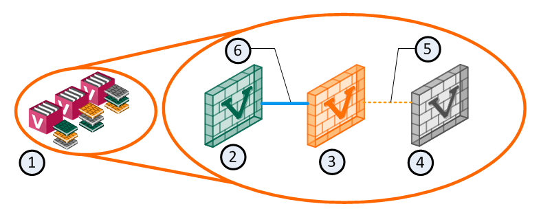
Virtual System States
VSLS adds a Backup state to the existing Active and Standby states. The Backup state contains the latest configuration settings for each Virtual System, but does not receive state table synchronization. The figure below illustrates the relationship between Virtual System states.
|
Item |
Description |
|
1 |
VSX Cluster |
|
2 |
Virtual System 1 on VSX Cluster Member 1 is Active |
|
3 |
Virtual System 1 on VSX Cluster Member 2 is Standby |
|
4 |
Virtual System 1 on VSX Cluster Member 3 is Backup |
|
5 |
Policy updates only |
|
6 |
State tables are synchronized |
Each Virtual System peer in a VSLS cluster is replicated on all VSX Cluster Members, and each copy exists in a different state. The Active and Standby states are synchronized, so that the Standby peer can immediately become Active in the event of a failure of the Active Virtual System or VSX Cluster Member. When this happens, the Backup peer becomes the Standby, and immediately synchronizes with the new Active Virtual System.
VSLS reduces the load on the synchronization network by not synchronizing the Backup Virtual System state tables with the Active Virtual System until a failover occurs.
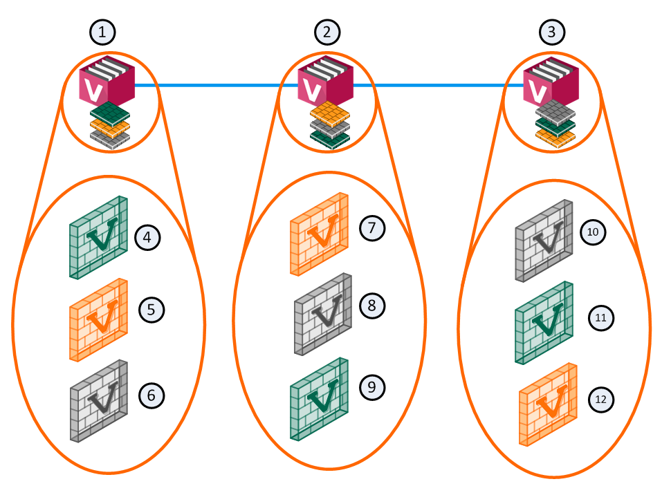
Normalized VSLS Deployment Scenario
For example, you can have three VSX Cluster Members, each with three Virtual Systems. In this configuration, an equalized Load Sharing deployment could have one Active Virtual System on each VSX Cluster Member.
|
Item |
Description |
|
Item |
Description |
|
1 |
VSX Cluster Member 1 |
|
8 |
Virtual System 2 is Backup |
|
2 |
VSX Cluster Member 2 |
|
9 |
Virtual System 3 is Active |
|
3 |
VSX Cluster Member 3 |
|
10 |
Virtual System 1 is Backup |
|
4 |
Virtual System 1 is Active |
|
11 |
Virtual System 2 is Active |
|
5 |
Virtual System 2 is Standby |
|
12 |
Virtual System 3 is Standby |
|
6 |
Virtual System 3 is Backup |
|
|
Sync Network |
|
7 |
Virtual System 1 is Standby |
|
|
|

A different VSX Cluster Member can host the Active state of each Virtual System. This distribution of Virtual Systems spreads the load among the VSX Cluster Members. When a Virtual System is created, the system automatically creates Standby and Backup states and distributes them among the other VSX Cluster Members.
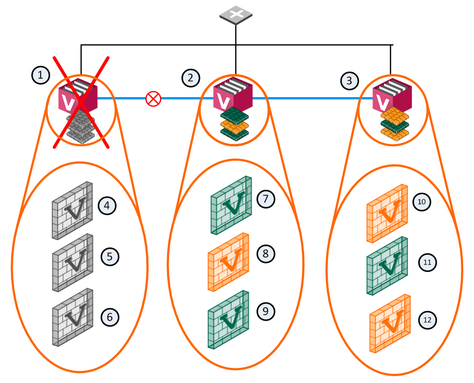
Member Failure Scenario
In the event that a member fails or experiences a connectivity problem, VSLS detects the problem and routes traffic for the affected Virtual Systems to their respective standby Virtual Systems. Standby Virtual Systems, which are fully synchronized with their active peers, change immediately to the active state and preserve active connections. At the same time, the backup Virtual Systems switch to standby, and synchronize fully with the newly active Virtual Systems.
|
Item |
Description |
|
Item |
Description |
|
1 |
VSX Cluster Member 1 |
|
8 |
Virtual System 2 is Standby |
|
2 |
VSX Cluster Member 2 |
|
9 |
Virtual System 3 is Active |
|
3 |
VSX Cluster Member 3 |
|
10 |
Virtual System 1 is Standby |
|
4 |
Virtual System 1 is Down |
|
11 |
Virtual System 2 is Active |
|
5 |
Virtual System 2 is Down |
|
12 |
Virtual System 3 is Standby |
|
6 |
Virtual System 3 is Down |
|
|
Sync Network |
|
7 |
Virtual System 1 is Active |
|
|
Network Traffic |

In this scenario, VSX Cluster Member 1 fails and its Active and Standby Virtual Systems fail over to VSX Cluster Member 2 and VSX Cluster Member 3. The Active Virtual System (VS1) moves to VSX Cluster Member 2 and directs all VS1 traffic itself. Its Backup peer on VSX Cluster Member 3 synchronizes with the new Active Virtual System and becomes the Standby.
VS2 on VSX Cluster Member 2 becomes the Standby and synchronizes with the Active peer on VSX Cluster Member 3. For VS3, the Active and Standby peers remain the same.
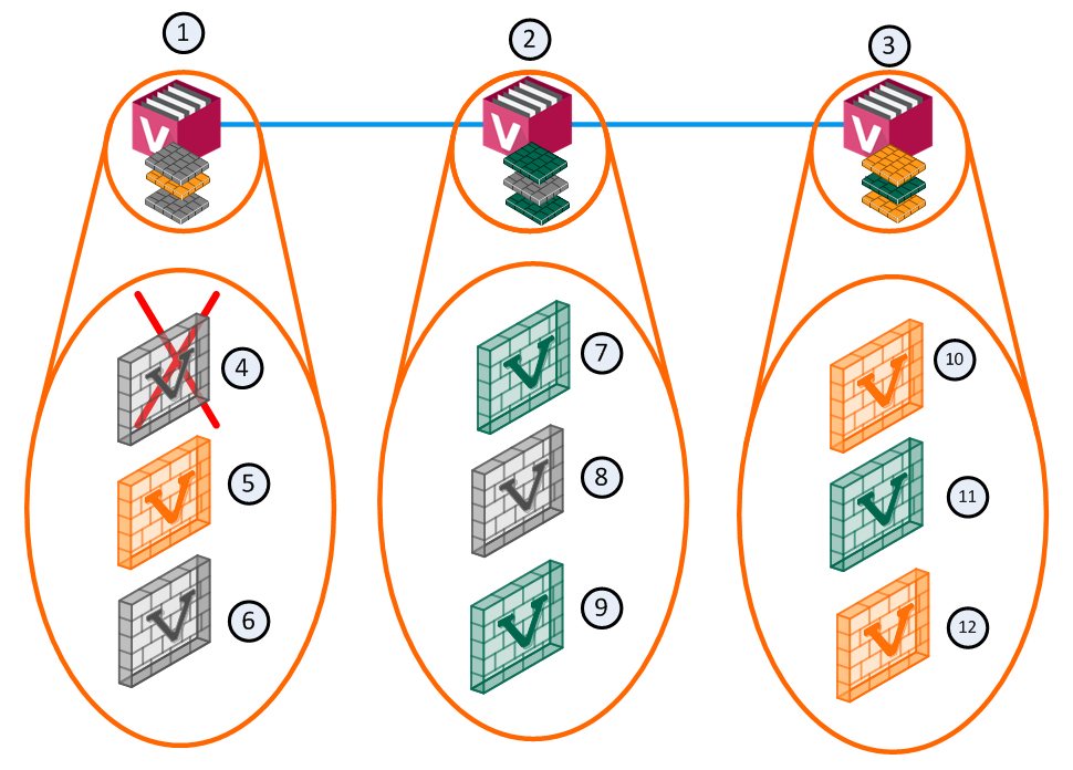
Virtual System Failure Scenario
In a failure scenario where an active Virtual System fails on one member, but the standby and backup Virtual Systems remain up: the active Virtual System fails over to its standby peer, and its backup becomes the standby. The new standby synchronizes with the new active member.
|
Item |
Description |
|
Item |
Description |
|
1 |
Member 1 |
|
8 |
VS 2 Backup |
|
2 |
Member 2 |
|
9 |
VS 3 Active |
|
3 |
Member 3 |
|
10 |
VS 1 Standby |
|
4 |
VS 1 Down |
|
11 |
VS 2 Active |
|
5 |
VS 2 Standby |
|
12 |
VS 3 Standby |
|
6 |
VS 3 Backup |
|
|
Sync Network |
|
7 |
VS 1 Active |
|
|
|
All other Virtual Systems continue to function normally and no failover occurs.
Failure Recovery
When the failed VSX Cluster Member or Virtual System comes back online, the system returns to its original Load Sharing configuration.