ISP Redundancy
Introduction
ISP Redundancy connects a Security Gateway![]() Dedicated Check Point server that runs Check Point software to inspect traffic and enforce Security Policies for connected network resources. to the Internet through redundant Internet Service Provider (ISP) links.
Dedicated Check Point server that runs Check Point software to inspect traffic and enforce Security Policies for connected network resources. to the Internet through redundant Internet Service Provider (ISP) links.
ISP Redundancy monitors the ISP links and chooses the best current link.
|
|
Notes:
|

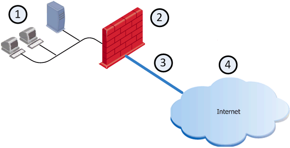
Example of a typical deployment with one ISP link
|
Item |
Description |
|---|---|
|
1 |
Internal network |
|
2 |
|
|
3 |
ISP |
|
4 |
Internet |
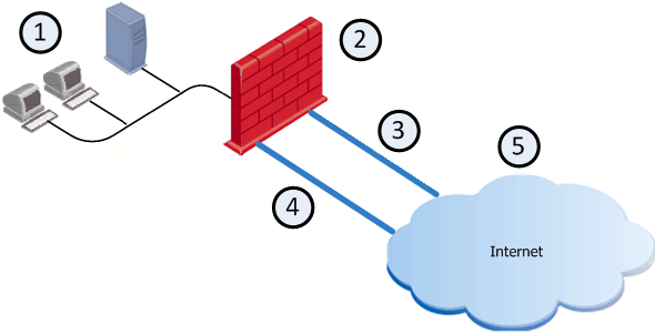
Example of a typical deployment with two dedicated physical interfaces for two ISP links
|
|
Best Practice - We recommend this deployment, because it is simpler than deployment with one dedicated physical interface. |

|
Item |
Description |
|---|---|
|
1 |
Internal network |
|
2 |
Security Gateway (Security Group) |
|
3 |
ISP A |
|
4 |
ISP B |
|
5 |
Internet |
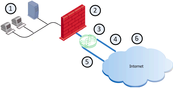
Example of a typical deployment with one dedicated physical interface for two ISP links
If only one external interface is available on the Security Gateway, you can configure two subnets on the same external interface.
(See the R80.20SP Quantum Scalable Chassis Gaia Administration Guide > Chapter Network Management > Section Network Interfaces > Section Aliases.)
Both ISP links are then connected to the same Security Gateway interface, but to different next hop routers, usually through a switch.
|
Item |
Description |
|---|---|
|
1 |
Internal network |
|
2 |
Security Gateway (Security Group) |
|
3 |
Switch |
|
4 |
ISP A |
|
5 |
ISP B |
|
6 |
Internet |
ISP Redundancy Modes
ISP Redundancy configuration modes control the behavior of outgoing connections from internal clients to the Internet:
|
Mode |
Description |
|---|---|
|
Load Sharing |
Uses the two links to distribute load of connections. Connections coming in are alternated. You can configure best relative loads for the links (set a faster link to handle more load). New connections are randomly assigned to a link. If one link fails, the other link takes the load. In this mode, incoming connections can reach the application servers through either ISP link because the Security Group can answer DNS requests for the IP address of internal servers with IP addresses from both ISPs by alternating their order. |
|
Primary/Backup |
Uses one link for connections. It switches to the Backup link if the Primary link fails. When the Primary link is restored, new connections are assigned to it. Existing connections continue on the Backup link until they are complete. In this mode, incoming connections (from the Internet to application servers in the DMZ or internal networks) also benefit, because the Security Group returns packets using the same ISP Link, through which the connection was initiated. |
|
|
Best Practice:
|
Outgoing Connections
-
In ISP Redundancy Load Sharing mode, outgoing traffic that exits the Security Group on its way to the Internet is distributed between the ISP Links. You can set a relative weight for how much it is necessary to use each of the ISP Links.
For example, if one link is faster, it can be configured to route more traffic across that ISP link than the other.
-
In ISP Redundancy Primary/Backup mode, outgoing traffic uses an active primary link.
Hide NAT is used to change the source address of outgoing packets to the address of the interface, through which the packet leaves the Security Group. This allows return packets to be automatically routed through the same ISP link, because their destination address is the address of the correct link. Hide NAT is configured by the administrator.
Incoming Connections
For external users to make incoming connections, the administrator must give each application server two routable IP addresses, one for each ISP.
The administrator must also configure Static NAT to translate the routable addresses to the real server address.
If the servers handle different services (for example, HTTP and FTP), you can use NAT to employ only two routable IP addresses for all the publicly available servers.
External clients use one of the two addresses. In order to connect, the clients must be able to resolve the DNS name of the server to the correct IP address.
|
|
Note - In the following example, the subnets 172.16.0.0/24 and 192.168.0.0/24 represent public routable addresses. |
In the following example, the Web server www.example.com is assigned an IP address from each ISP:
-
192.168.1.2 from ISP A
-
172.16.2.2 from ISP B
If the ISP Link A is down, then IP address 192.168.1.2 becomes unavailable, and the clients must be able to resolve the URL www.example.com to the IP address 172.16.2.2.
Example chain of events:
-
When an external client on the Internet contacts www.example.com, the client sends a DNS query for the IP address of this URL.
The DNS query reaches the Security Group.
The Security Group has a built-in mini-DNS server that can be configured to intercept DNS queries (of Type A) for servers in its domain.
-
The Security Group intercepts a DNS query that arrives at an interface that belongs to one of the ISP links.
-
If the Security Group recognizes the name of the host, it sends one of the following replies:
-
In ISP Redundancy Primary/Backup mode, the Security Group replies only with the IP addresses associated with the Primary ISP link, as long as the Primary ISP link is active.
-
In ISP Redundancy Load Sharing mode, the Security Group replies with two IP addresses, alternating their order.
-
-
If the Security Group is unable to handle DNS requests (for example, it may not recognize the host name), it passes the DNS query to its original destination or the DNS server of the domain example.com.
-
When the external client receives the reply to its DNS query, it opens a connection.
When the packets reach the Security Group, the Security Group uses Static NAT to translate the destination IP address 192.168.1.2 or 172.16.2.2 to the real server IP address 10.0.0.2.
-
The Security Group routes the reply packets from the server to the client through the same ISP link that was used to initiate the connection.