|
|
|
This section includes advanced NAT settings.
This section discusses how to configure NAT in some network deployments.
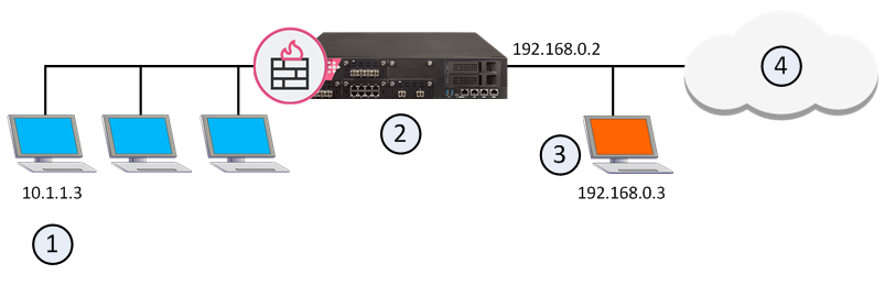
Giving a computer in the internal network an external IP address using NAT makes that machine appear to the Internet to be on the external network, or the Internet side of the firewall. When NAT is configured automatically, the Security Gateway replies on behalf of translated network objects to ARP requests from the Internet router for the address of the internal machine.
Item |
Description |
|---|---|
1 |
Computer in the internal network with IP address 10.1.1.3 |
2 |
Security Gateway with external interface IP address 192.168.0.2 responds to arp requests on behalf of translated internal objects> |
3 |
Translated IP Address on the external network, or the Internet side of the firewall 192.168.0.3 |
4 |
Internet |
If you are using manual rules, you must configure proxy ARPs to associate the translated IP address with the MAC address of the Security Gateway interface that is on the same network as the translated addresses.
For more about configuring Proxy ARP for IPv4 Manual NAT, see sk30197.
For more about configuring Proxy NDP for IPv6 Manual NAT, see sk91905.
NAT is performed after Anti-Spoofing checks, which are performed only on the source IP address of the packet. This means that spoofing protection is configured on the interfaces of the Security Gateway in the same way as NAT.
When communicating within a VPN, it is normally not necessary to perform NAT. You can disable NAT in a VPN tunnel with a single click in the VPN community object. Disabling NAT in a VPN tunnel by defining a NAT rule slows down the performance of the VPN.
The following sections describe how to allow connections in both directions between statically translated objects (hosts, networks or address ranges) on different Security Gateway interfaces.
If NAT is defined through the network object (as opposed to using Manual NAT Rules), then you must ensure that bidirectional NAT is enabled.
If two internal networks have overlapping (or partially overlapping) IP addresses, Security Gateway enables:
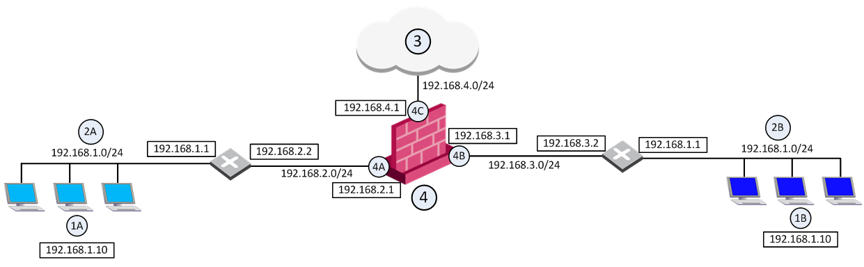
For example, assume both Network 2A and Network 2B share the same address space (192.168.1.0/24), therefore standard NAT cannot be used to enable communication between the two networks. Instead, overlapping NAT must be performed on a per interface basis.
Users in Network 2A who want to communicate with users in Network 2B must use the 192.168.30.0/24 network as a destination. Users in Network 2B who want to communicate with users in Network 2A must use the 192.168.20.0/24 network as a destination.
The Security Gateway (4) translates the IP addresses in the following way for each individual interface:
Overlapping NAT is not configured for this interface. Instead, use NAT Hide in the normal way (not on a per-interface basis) to hide source addresses behind the interface's IP address (192.168.4.1).
This section describes how to enable communication between internal networks, and between an internal network and the Internet
If user 1A, at IP address 192.168.1.10 in Network 2A, wants to connect to user 1B, at IP address 192.168.1.10 (the same IP address) in Network 2B, user 1A opens a connection to the IP address 192.168.30.10.
Communication Between Internal Networks
Step |
Source IP address |
Destination IP address |
|---|---|---|
Interface 4A — before NAT |
192.168.1.10 |
192.168.30.10 |
Interface 4A — after NAT |
192.168.20.10 |
192.168.30.10 |
Security Gateway enforces the security policy for packets from network 192.168.20.0/24 to network 192.168.30.0/24. |
||
Interface 4B — before NAT |
192.168.20.10 |
192.168.30.10 |
Interface 4B — after NAT |
192.168.20.10 |
192.168.1.10 |
If user 1A, at IP address 192.168.1.10 in network 2A, connects to IP address 192.0.2.10 on the Internet (3).
Communication Between an Internal Network and the Internet
Step |
Source IP address |
Destination IP address |
|---|---|---|
Interface 4A — before NAT |
192.168.1.10 |
192.0.2.10 |
Interface 4A — after NAT |
192.168.20.10 |
192.0.2.10 |
The Security Gateway (4) enforces the security policy for packets from network 192.168.20.0/24 to the Internet (3). |
||
Interface 4C — before NAT |
192.168.20.10 |
192.0.2.10 |
Interface 4C — after NAT Hide |
192.168.4.1 |
192.0.2.10 |
To allow routing from Network 2A to Network 2B, routing must be configured on the Security Gateway.
These sections contain sample routing commands for Windows and Linux operating systems (for other operating systems, use the equivalent commands).
To activate the overlapping NAT feature, use GuiDBedit Tool (see sk13009), or dbedit (see skI3301). In the sample network configuration, the per interface values for interface 4A and interface 4B are set in the following way:
Sample Network Configuration: Interface Configuration
Parameter |
Value |
|---|---|
enable_overlapping_nat |
true |
overlap_nat_dst_ipaddr |
The overlapping IP addresses (before NAT). In the sample network configuration, 192.168.1.0 for both interfaces. |
overlap_nat_src_ipaddr |
The IP addresses after NAT. In the sample network configuration, 192.168.20.0 for interface 4A, and 192.168.30.0 for interface 4B. |
overlap_nat_netmask |
The net mask of the overlapping IP addresses. In the sample network configuration, 255.255.255.0. |
The Security Management Server sometimes uses a private IP address (as listed in RFC 1918) or some other non-routable IP address, because of the lack of public IP addresses.
NAT (Static or Hide) for the Security Management Server IP address can be configured in one click, while still allowing connectivity with managed gateways. All gateways can be controlled from the Security Management Server, and logs can be sent to the Security Management Server. NAT can also be configured for a Management High Availability server and a Log Server.
Note - Security Management behind NAT is not supported for deployments where the Security Management Server also acts as a gateway and must be addressed from outside the NATed domain, for example, when it receives SAM commands.
In a typical Security Management Behind NAT scenario: the Security Management Server (1) is in a network on which Network Address Translation is performed (the "NATed network"). The Security Management Server can control Security Gateways inside the NATed network, on the border between the NATed network and the outside world and outside the NATed network.
Item |
Description |
|---|---|
1 |
Primary_Security_Management object with IP address 10.0.0.1. Translated address 192.168.55.1 |
In ordinary Hide NAT configurations, connections cannot be established from the external side the NAT A Security Gateway. However, when using Hide NAT on the Security Management Server, gateways can send logs to the Security Management Server.
When using the Security Management behind NAT feature, the remote gateway automatically selects the Security Management address to be addressed and simultaneously applies NAT considerations.
To enable NAT for the Security Management Server:
Sometimes the gateway contacts the Security Management Server with an address that does not correspond to the deployment of the remote gateway. For example:
To define masters and loggers, select Use local definitions for Log Servers and Use local definitions for Masters and specify the correct IP addresses on the gateway.
This solution encompasses different scenarios:
Notes:
To configure the Security Management Server object:
To configure the Security Gateway object:
An IP Pool is a range of IP addresses (an address range, a network or a group of one of these objects) that is routable to the gateway. IP Pool NAT ensures proper routing for encrypted connections for the following two connection scenarios:
When a connection is opened from a Remote Access Client or a client behind a gateway, to a server behind the MEP Gateways, the packets are routed through one of the MEP gateways. Return packets in the connection must be routed back through the same gateway in order to maintain the connection. To ensure that this occurs, each of the MEP gateways maintains a pool of IP addresses that are routable to the gateway. When a connection is opened to a server, the gateway substitutes an IP address from the IP pool for the source IP address. Reply packets from the server return to the gateway, which restores the original source IP address and forwards the packets to the source.
You can define a separate IP address pool on one or more of the gateway interfaces instead of defining a single pool of IPs for the gateway.
Defining an IP pool per interface solves routing issues that occur when the gateway has more than two interfaces. Sometimes it is necessary that reply packets return to the gateway through the same gateway interface. This illustration shows one of the MEP Gateways in a Remote Access Client to MEP (Multiple Entry Point) gateway deployment.
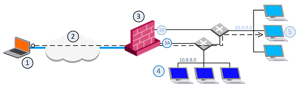
Item |
Description |
|---|---|
1 |
Packets from source host: Source: Original |
2 |
VPN tunnel through the Internet |
3 |
MEP Gateway |
3A |
IP Pool 1 packets: Source: 10.55.8.x |
3B |
IP Pool 2 packets: Source: 10.55.10.x |
4 |
Internal network 10.8.8.0 |
5 |
Target host in internal network 10.10.10.0 |
If a remote client opens a connection to the internal network, reply packets from hosts inside the internal networks are routed to the correct gateway interface through the use of static IP pool NAT addresses.
The remote client's IP address is NATed to an address in the IP pool on one of the gateway interfaces. The addresses in the IP pool can be routed only through that gateway interface so that all reply packets from the target host are returned only to that interface. Therefore, it is important that the IP NAT pools of the interfaces do not overlap.
When the packet returns to the gateway interface, the gateway restores the remote peer's source IP address.
The routing tables on the routers that lie behind the gateway must be edited so that addresses from a gateway IP pool are returned to the correct gateway interface.
Switching between IP Pool NAT per gateway and IP Pool NAT per interface and then installing the security policy deletes all IP Pool allocation and all NATed connections.
IP Pool NAT can be used both for encrypted (VPN) and non-encrypted (decrypted by the gateway) connections.
Note - To enable IP Pool NAT for clear connections through the gateway, configure INSPECT changes in the user.def file (see sk98239). Contact Check Point Technical Support.
For non-encrypted connections, IP Pool NAT has the following advantages over Hide NAT:
Because of these advantages, you can specify that IP Pool NAT has priority over Hide NAT, if both match the same connection. Hide NAT is only applied if the IP pool is used up.
The order of NAT priorities are:
Since Static NAT has all of the advantages of IP Pool NAT and more, it has a higher priority than the other NAT methods.
IP Pool addresses can be reused for different destinations, which makes more efficient use of the addresses in the pool. If a pool contains N addresses, then any number of clients can be assigned an IP from the pool as long as there are no more than N clients per server.
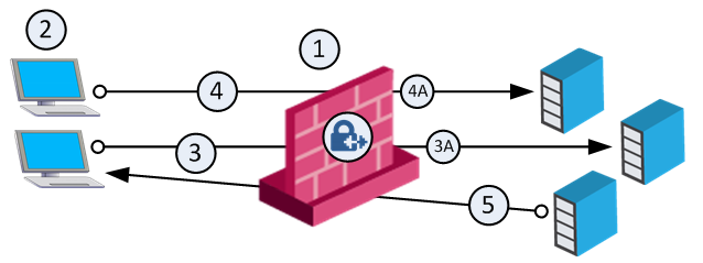
Using IP Pool allocation per destination, two different clients can receive the same IP from the pool as long as they communicate with different servers (connections 1 and 2). When reusing addresses from the IP Pool, back connections are supported from the original server only (connection 3). This means that connections back to the client can be opened only from the specific server to which the connection was opened.
Item |
Description |
|---|---|
1 |
Gateway with IP Pool addresses A to Z |
2 |
Clients. Source: Original |
3A |
NATed packet from connection 3. Source: A |
4A |
NATed packet from connection 4. Source: A |
5A |
NATed packet from reply connection 5. Source: Original |
6A |
This server cannot open a connection with Destination A back to the client. |
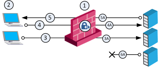
The default Do not reuse IP Pool NAT behavior means that each IP address in the IP Pool is used once (connections 1 and 2 in the following illustration). In this mode, if an IP pool contains 20 addresses, up to 20 different clients can be NATed and back connections can be opened from any source to the client (connection 3).
Item |
Description |
|---|---|
1 |
Gateway with IP Pool addresses A to Z. |
2 |
Clients. Source: Original |
3A |
NATed packet from connection 3. Source: A |
4A |
NATed packet from connection 4. Source: Z |
5 |
Connection. Source: Original |
Switching between the Reuse and Do not reuse modes and then installing the security policy, deletes all IP Pool allocations and all NATed connections.
To configure IP Pool NAT:
The Address Range Properties window opens.
IP Pools for gateway clusters are configured in two places in SmartConsole:
The basis of Site-to-Site VPN is the encrypted VPN tunnel. Two Security Gateways negotiate a link and create a VPN tunnel and each tunnel can contain more than one VPN connection. One Security Gateway can maintain more than one VPN tunnel at the same time.
Item |
Description |
|---|---|
A, B |
Security Gateways |
2 |
VPN tunnel |
3 |
Internal network in VPN domain |
4 |
Host 4 |
5 |
Host 5 |
In this sample VPN deployment, Host 4 and Host 5 securely send data to each other. The Security Gateways perform IKE negotiation and create a VPN tunnel. They use the IPsec protocol to encrypt and decrypt data that is sent between Host 4 and Host 5.
VPN Workflow
Host 4 sends packet |
|
Firewalls A & B create VPN tunnel |
|
Firewall A encrypts data |
|
|
|
|
|
Host 5 receives unencrypted data |
|
Firewall B decrypts data |
|
Encrypted data is sent through VPN tunnel |
A VPN Domain is a collection of internal networks that use Security Gateways to send and receive VPN traffic. Define the resources that are included in the VPN Domain for each Security Gateway. Then join the Security Gateways into a VPN community - collection of VPN tunnels and their attributes. Network resources of different VPN Domains can securely communicate with each other through VPN tunnels that terminate at the Security Gateways in the VPN communities.
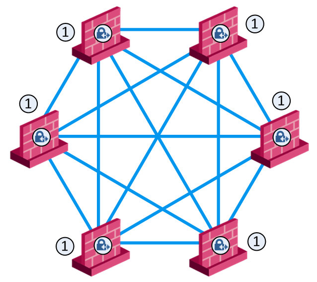
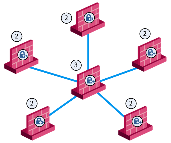
VPN communities are based on Star and Mesh topologies. In a Mesh community, there are VPN tunnels between each pair of Security Gateway. In a Star community, each satellite Security Gateway has a VPN tunnel to the central Security Gateway, but not to other Security Gateways in the community.
Note - Global VPN Communities are not supported in this release.
Mesh Topology |
Star Topology |
Item |
Description |
|---|---|
1 |
Security Gateway |
2 |
Satellite Security Gateways |
3 |
Central Security Gateway |
This section explains how to configure a VPN star community. This deployment lets the satellite Security Gateways connect to the internal network of the central Security Gateway. The internal network object is named: Internal-network.
To create a new VPN Star Community:
The New Star Community window opens.
To configure star VPN for the Security Gateways:
For each Security Gateway in the VPN community, follow these configuration steps.
The gateway properties window opens.
The Add this Gateway to Community window opens.
After you create a community and configure Security Gateways, add those Security Gateways to the community as a center or as a satellite gateway.
To add a Security Gateway to a new star community:
The Star Community window opens.
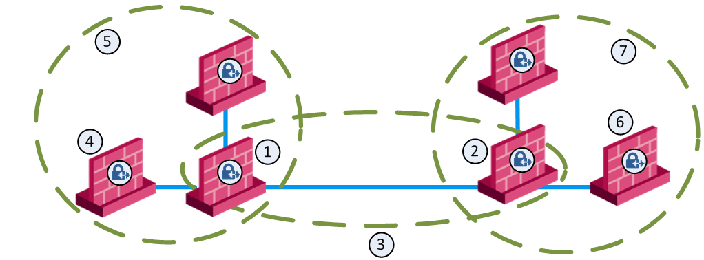
Item |
Description |
|---|---|
1 |
London Security Gateway |
2 |
New York Security Gateway |
3 |
London - New York Mesh community |
4 |
London company partner (external network) |
5 |
London Star community |
6 |
New York company partner (external network) |
7 |
New York Star community |
This deployment is composed of a Mesh community for London and New York Security Gateways that share internal networks. The Security Gateways for external networks of company partners do not have access to the London and New York internal networks. However, the Star VPN communities let the company partners access the internal networks of the sites that they work with.
To allow VPN connections between Security Gateways in specific VPN communities, add Access Control rules that accept such connections.
To allow all VPN traffic to hosts and clients on the internal networks of a specific VPN community, select these options in the Encrypted Traffic section of the properties configuration window for that VPN Community:
This table shows sample VPN rules for an Access Control Rule Base. (The Action, Track and Time columns are not shown. Action is set to Allow, Track is set to Log, and Time is set to Any.)
No. |
Name |
Source |
Destination |
VPN |
Service |
Install On |
|---|---|---|---|---|---|---|
1 |
- |
Any |
NEGATED Member Gateways |
BranchOffices |
Any |
BranchOffices |
2 |
Site-to-site VPN |
Any |
Any |
All_GwToGw |
FTP-port |
Policy Targets |
3 |
Remote access |
Any |
Any |
RemoteAccess |
HTTP |
Policy Targets |
BranchOffices VPN community and the LondonOffices VPN community. This rule is installed on all the Security Gateways in these communities. It allows all VPN traffic to hosts and clients on the internal networks of these communities. Traffic that is sent to the Security Gateways in these VPN communities is dropped.Note - This automatic rule can apply to more than one VPN community.
To learn more about Site to Site VPN, see the R80.10 Site to Site VPN Administration Guide.
If employees remotely access sensitive information from different locations and devices, system administrators must make sure that this access does not become a security vulnerability. Check Point's Remote Access VPN solutions let you create a VPN tunnel between a remote user and the internal network. The Mobile Access Software Blade extends the functionality of Remote Access solutions to include many clients and deployments.
The IPsec VPN Software Blade lets the Firewall overcome connectivity challenges for remote clients. Use VPN connectivity modes to make sure that remote users can connect to the VPN tunnels. These are some examples of connectivity challenges:
Office Mode
Remote users can be assigned the same or non-routable IP addresses from the local ISP. Office Mode solves these routing problems and encapsulates the IP packets with an available IP address from the internal network. Remote users can send traffic as if they are in the office and do not have VPN routing problems.
Visitor Mode
Remote users can be restricted to use HTTP and HTTPS traffic only. Visitor Mode lets these users tunnel all protocols with a regular TCP connection on port 443.
Use SmartConsole to enable and configure the Security Gateway for remote access VPN connections. Then add the remote user information to the Security Management Server: create and configure an LDAP Account Unit or enter the information in the SmartConsole user database. You can also configure the Firewall to authenticate the remote users. Define the Firewall access control and encryption rules. Create the LDAP group or user group object that is used for the Firewall rules. Then create and configure the encryption settings for the VPN community object. Add the access rules to the Firewall Rule Base to allow VPN traffic to the internal networks.
|
|
Enable remote access VPN |
|
|
|
|
|
|
|
Configure LDAP |
LDAP
|
Manage Users? |
Smart |
Configure users in SmartConsole database |
|
|
|
|
|
Configure user authentication |
|
|
|
Configure user authentication |
|
|
|
|
|
Create LDAP user |
|
Create VPN Community |
|
Create user |
|
|
|
|
|
|
|
Configure rules for VPN access in Firewall Rule Base |
|
|
|
|
|
|
|
|
|
Install policy |
|
|
Make sure that the VPN Software Blade is enabled before you configure the Remote Access community.
To configure the Security Gateway for Remote Access:
The gateway window opens and shows the General Properties page.
The page shows the VPN communities that the Security Gateway is participating.
Note - Office Mode support is mandatory on the Security Gateway side.
To learn more about Remote Access VPN, see the R80.10 VPN Remote Access Administration Guide.
Check Point Mobile Access lets remote users easily and securely use the Internet to connect to internal networks. Remote users start a standard HTTPS request to the Mobile Access Security Gateway, and authenticate with one or more secure authentication methods.
The Mobile Access Portal lets mobile and remote workers connect easily and securely to critical resources over the internet. Check Point Mobile Apps enable secure encrypted communication from unmanaged smartphones and tablets to your corporate resources. Access can include internal apps, email, calendar, and contacts.
To include access to Mobile Access applications in the Rule Base, include the Mobile Application in the Services & Applications column.
To give access to resources through specified remote access clients, create Access Roles for the clients and include them in the Source column of a rule.