


|
|
|
ClusterXL uses unique physical IP and MAC addresses for each Cluster Member, and a virtual IP addresses for the cluster itself. Cluster interface addresses do not belong to any real member interface.
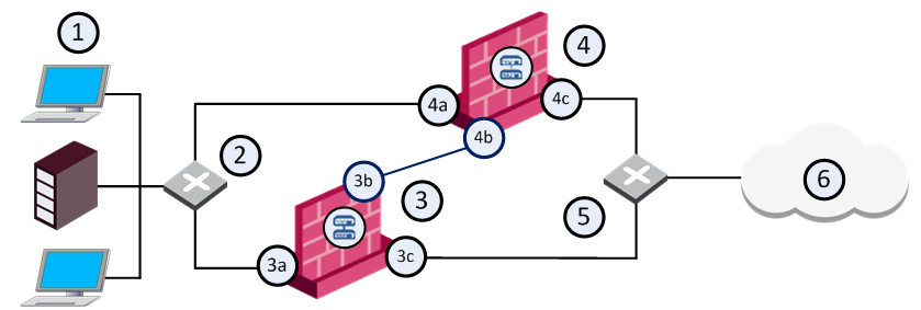
The following diagram illustrates a two-member ClusterXL cluster, showing the cluster Virtual IP addresses and members physical IP addresses. This sample deployment is used in many of the examples presented in this chapter.
Item |
Description |
|---|---|
1 |
Internal network |
2 |
Internal switch (internal cluster IP address 10.10.0.100) |
3 |
Security Gateway - Cluster Member A |
3a |
Virtual interface to the internal network (10.10.0.1) |
3b |
Interface to the Cluster Sync network (10.0.10.1) |
3c |
Virtual interface to the external network (192.168.10.1) |
4 |
Security Gateway - Cluster Member B |
4a |
Virtual interface to the internal network (10.10.0.2) |
4b |
Interface to the Cluster Sync network (10.0.10.2) |
4c |
Virtual interface to the external network (192.168.10.2) |
5 |
External switch (external cluster IP address 192.168.10.100) |
6 |
Internet |
Each Cluster Member has three interfaces: one external interface, one internal interface, and one for synchronization. Cluster Member interfaces facing in each direction are connected via a hub or switch.
All Cluster Member interfaces facing the same direction must be in the same network. For example, there must not be a router between Cluster Members.
The Management Server can be located anywhere, and connection should be established to either the internal or external cluster IP addresses.
These sections present ClusterXL configuration concepts shown in the example.
Note - In these examples, RFC 1918 private addresses in the range 192.168.0.0 to 192.168.255.255 are treated as public IP addresses.
The guidelines for configuring each Cluster Member are as follows:
All members within the cluster must have at least three interfaces:
All interfaces pointing in a certain direction must be on the same network.
For example, in the previous illustration, there are two Cluster Members, Member_A and Member_B. Each has an interface with an IP address facing the Internet through a hub or a switch. This is the external interface with IP address 192.168.10.1 on Member_A and IP address 192.168.10.2 on Member_B.
Note - This release presents an option to use only two interfaces per member, one external and one internal, and to run synchronization over the internal interface. We do not recommend this configuration. It should be used for backup only.
In the previous illustration, the IP address of the cluster is 192.168.10.100.
The cluster has one external virtual IP address and one internal virtual IP address. The external IP address is 192.168.10.100, and the internal IP address is 10.10.0.100.
The previous illustration shows a synchronization interface with a unique IP address on each Cluster Member - IP 10.0.10.1 on Member_A and IP 10.0.10.2 on Member_B.
Only one public IP address is required in a ClusterXL cluster, for the virtual cluster interface that faces the Internet. Physical IP addresses of all Cluster Members can be private.
Configuring different subnets for the cluster IP addresses and the members IP addresses is useful in order to:

