NAT and the Correction Layer on a VSX Gateway
In a VSX Gateway, the guidelines in NAT and the Correction Layer on Security Gateway apply to each Virtual System individually. In particular, an entire session should be handled by the same SGM by a given Virtual System. When a Virtual Router or Virtual Switch ("Junction") connects several Virtual Systems, the same session may be handled by one Virtual System on one SGM, and by another Virtual System on a different SGM.
When a packet reaches a Virtual System from a Junction, the system VSX Stateless Correction Layer rechecks the distribution according to the Warp interface’s Distribution Mode. It can decide to forward the packet to a different SGM.
In addition, on each Virtual System the system Correction Layer, which is stateful, can forward session’s packets, similar to Security Gateway.
All forwarding operations have a performance impact. Therefore, the Distribution Mode configuration should minimize forwarding operations.
To achieve optimal distribution between SGMs on the VSX Gateway:
- If you do not use NAT rules on any Virtual System, set the General Distribution Mode.
- If you use NAT rules on at least one Virtual System, set the hidden network(s) to User Mode, and the destination network(s) to Network Mode.
- On the remaining Virtual Systems that do not use NAT rules, set internal network(s) to User Mode, and the external network(s) to Network Mode.
Common Scenarios with a Virtual Router
These are examples for common scenarios with a Virtual Router. The examples also apply to a Virtual Switch. The examples show the recommended Distribution Mode configuration for optimal performance.
In both examples there are two Virtual Systems (VS1 and VS2), and one Virtual Router (VR). VS1 and VS2 protect internal networks A and B, respectively. VR connects VS1, VS2, and network C, which is an external network. VS1 has NAT rules that hide Network A behind it. VS2 does not use NAT rules.
Example 1
In this example most of the traffic is from Networks A and B to Network C.
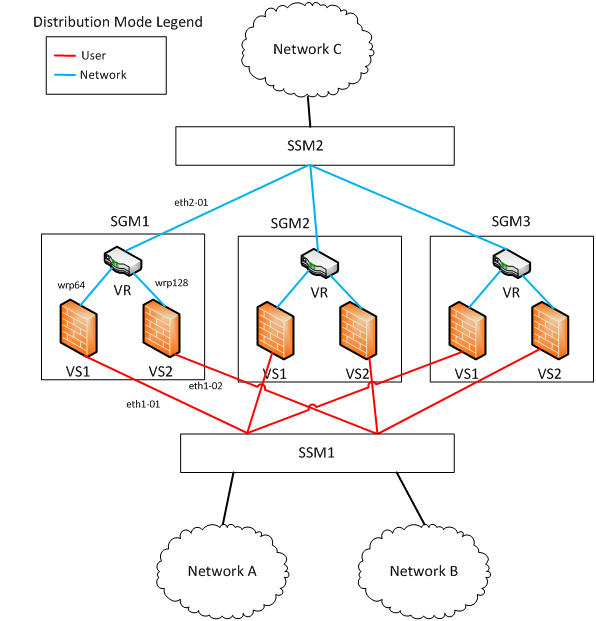
Because only VS1 uses NAT rules, configure the interfaces’ Distribution Mode according to it. VS1 hides Network A. Therefore the Distribution Mode of eth1-01 is User.
Traffic from Network A leaves VS1 on wrp64, so the Distribution Mode of wrp64 is the opposite network.
Interface eth2_01 is configured to Network as well, because the VR does not change the packet.
Packets from Network A to Network C are distributed by their destination (User).
Packets from Network C to Network A are distributed by their source (Network). Since eth2-01 and wrp64 have the same Distribution Mode, the VSX Stateless Correction Layer does not forward them to a different SGM. Therefore, the correction layer does not need forwarding operations.
Configure the Distribution Mode for VS2, which does not use NAT rules. Because the Distribution Mode of eth2_01 is Network, the Distribution Mode of wrp128 is also set to Network.
Finally, the Distribution Mode of eth1_02 is set to User (the opposite of wrp128). It is easy to see that with this configuration no forwarding operations are required by the correction Layer for traffic between Networks B and C.
Example 2
In this example most of the traffic is from Network A toward Network B, and from Network B toward Network C.
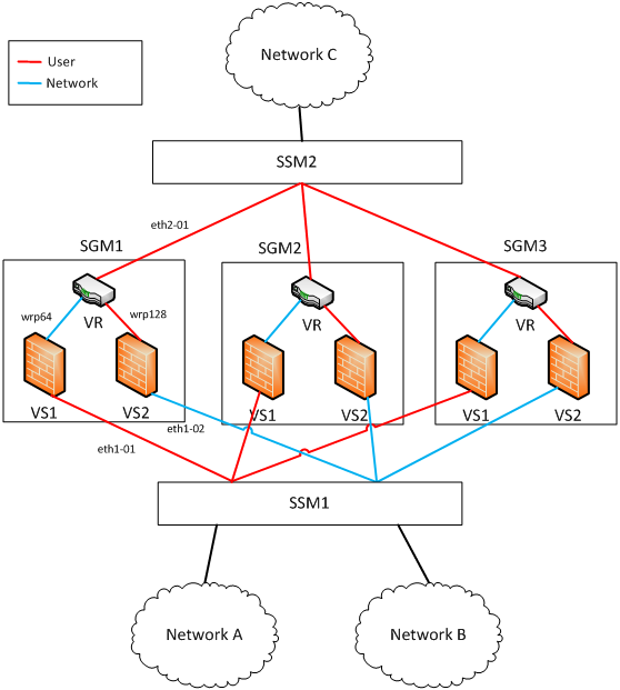
As in the previous example, because only VS1 uses NAT rules, configure the Distribution Mode of the interfaces according to VS1. VS1 hides Network A. Therefore the Distribution Mode of eth1-01 is User.
Traffic from Network A leaves VS1 on wrp64 so the Distribution Mode of wrp64 is the opposite: Network
Most of the traffic from Network A is toward Network B, meaning it is also inspected by VS2. To prevent forwarding by the system VSX Stateless Correction Layer, wrp128 has the same Distribution Mode as eth1-01. That is, the distribution for both is determined by the packet’s destination address, which is not changed by the NAT rules.
To complete the configuration of VS2, set the Distribution Mode of eth1-02 to Network (the opposite of wrp128).
Finally, set the Distribution Mode of eth2-01. Note that wrp64 is configured to Network, and wrp128 is configured to User. Because there is more traffic from Network B to Network C than from Network A to Network C, configure eth2-01 to User (same as wrp128).
With this configuration, the correction layer does not need forwarding operations for traffic between Networks B and C, or for traffic between Networks A and B.
|

