EA Feature: SD-WAN in Layer 2
This section describes an SD-WAN feature in the Early Availability stage.
|
|
Important:
|

This feature adds support for over Layer 2 between SD-WAN Security Gateways that are connected to the same subnet. For example, over an MPLS line.
Configuration
Step 1 - Configure the Next Hop
You can configure the required settings in Gaia Portal or in Gaia Clish:
-
With a web browser, connect to Gaia Portal on the Security Gateway / each Cluster Member.
-
Navigate to Network Management > Network Interfaces.
-
Double-click the relevant interface.
-
Click the SD-WAN tab.
-
Select Use as SD-WAN interface.
-
In the section Next Hop, select the applicable option based on how the peers of this specific interface are connected:
-
If all SD-WAN peers are connected over Layer 2:
Select No Next Hop (Layer-2 Only Interface).

Note - The option Accessible via NAT becomes disabled.
-
If some SD-WAN peers are connected over Layer 3 and some SD-WAN peers are connected over Layer 2:
Select Use the following Next Hop IP address and enter the relevant IP Address for the ISP, to which this interface connects.
Note - Based on the destination IP address, this SD-WAN Security Gateway automatically detects how to use the configured Next Hop:
-
If the destination IP address does not belong to the same subnet as the IP address of this interface, then the Security Gateway forwards the traffic to the configured Layer 3 Next Hop.
-
If the destination IP address belongs to the same subnet as the IP address of this interface, then the Security Gateway forwards the traffic to the relevant Layer 2 peer.
-
-
If all SD-WAN peers are connected over Layer 3:
Select Use the following Next Hop IP address and enter the relevant IP Address for the ISP, to which this interface connects.
-
-
Click OK.
-
Connect to the command line on the Security Gateway / each Cluster Member.
-
Log in.
-
If your default shell is the Expert mode, go to Gaia Clish:
clish -
For the applicable interface, configure the applicable next hop based on how the peers of this specific interface are connected:
-
If all SD-WAN peers are connected over Layer 2:
set interface <Name of Interface> sdwan next-hop l2-only -
If some SD-WAN peers are connected over Layer 3 and some SD-WAN peers are connected over Layer 2:
set interface <Name of Interface> sdwan next-hop <IP Address of ISP Next Hop>
Note - Based on the destination IP address, this SD-WAN Security Gateway automatically detects how to use the configured Next Hop:
-
If the destination IP address does not belong to the same subnet as the IP address of this interface, then the Security Gateway forwards the traffic to the configured Layer 3 Next Hop.
-
If the destination IP address belongs to the same subnet as the IP address of this interface, then the Security Gateway forwards the traffic to the relevant Layer 2 peer.
-
-
If all SD-WAN peers are connected over Layer 3:
set interface <Name of Interface> sdwan next-hop <IP Address of ISP Next Hop>
-
-
Save the configuration:
save config
Step 2 - Configure Circuit ID Values
For information, see SD-WAN Circuit ID.
By default:
-
The Circuit ID for a Public link is "0".
-
The Circuit ID for a Private link is "1".
Follow these guidelines to configure Circuit ID values:
When a Security Gateway has multiple Layer 2 links, you must override the default Circuit ID value and configure unique Circuit ID for each Layer 2 link.
Note - This does not apply to the Circuit ID 0, which is reserved as the default for Public links.
If you do not change the default Circuit ID values, different Layer 2 links will share the same Circuit ID value and will not differentiate between peer Security Gateways on different subnets when they create . Assigning distinct Circuit ID values ensures that are established only within the appropriate subnets.
Example diagram:
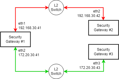
These pairs of interfaces must have unique Circuit ID value for the :
-
Between the interface
eth1on the Security Gateway #1 (192.168.30.41) and the interfaceeth2on the Security Gateway #2 (192.168.30.42). -
Between the interface
eth2on the Security Gateway #1 (172.20.30.41) and the interfaceeth3on the Security Gateway #3 (172.20.30.43).
By default, all these "Private" interfaces have the same Circuit ID value. As a result, they will try to establish with each other, although only specific pairs of interfaces should do this.
When the same interface on a Security Gateway connects both to Layer 3 peers (Public links) and to Layer 2 peers (Private links), there may be cases when it is necessary to override the default Circuit ID value and configure the same Circuit ID value on all relevant interfaces.
This ensures that the links can establish the necessary for both Layer 3 and Layer 2 communication.
If the Circuit ID values differ ("0" for Public links and "1" for Private links), the interfaces will be treated as separate circuits and will not be able to establish all the required with each other.
Example diagram:

These pairs of interfaces must have the same Circuit ID value for :
-
Layer 3:
Between the interface
eth1on the Security Gateway #1 (172.20.30.41), through a Router, and the interfaceeth2on the Security Gateway #2 (192.168.20.42). -
Layer 2:
Between the interface
eth1on the Security Gateway #1 (172.20.30.41), through a Switch, and the interfaceeth3on the Security Gateway #3 (172.20.30.43).
By default, the Layer 3 ("Public") interfaces and the Layer 2 ("Private") interfaces have different Circuit ID values. As a result, the interface eth1 on the Security Gateway #1 (172.20.30.41) will establish only with one type peers, although it should do this with both types of peers.
Step 3 - Configure WAN Link Mapping (only for Layer 2 peers)
For information, see WAN Link Mapping.
If all SD-WAN peers of a specific interface are connected over Layer 2, you must configure the WAN Link Mapping as follows:
-
In the Manage WAN Links panel, create a new link of type Private and configure it.
-
On the WAN Link Mapping page, go to the row for the Security Gateway / Cluster.
-
In the column "<Name of Private WAN Link>", click (+).
-
In the section Interface Mapping, select the applicable interface to which all SD-WAN peers are connected over Layer 2.
CPView output
If both Layer 3 and Layer 2 are used on the Security Gateway, then the CPView tool:
-
On the Advanced > SDWAN > Probing page, in the Nexthop Probing Results section, shows the results only for Layer 3 (does not show the results for Layer 2).
-
On the Advanced > SDWAN > Probing page, in the Overlay Probing Results section, shows the information for both Layer 3 and Layer 2.