Preparing an NDR Sensor
Overview
This section describes how to convert a Check Point Quantum Security Gateway![]() Dedicated Check Point server that runs Check Point software to inspect traffic and enforce Security Policies for connected network resources. appliance to an NDR
Dedicated Check Point server that runs Check Point software to inspect traffic and enforce Security Policies for connected network resources. appliance to an NDR![]() Network Detection and Response-Managed NDR sensor.
Network Detection and Response-Managed NDR sensor.
You can use the same process for an NDR sensor installed as a Virtual Machine in a cloud or on an Open Server![]() Physical computer manufactured and distributed by a company, other than Check Point..
Physical computer manufactured and distributed by a company, other than Check Point..
Supported Versions
-
R82
-
R81.20
-
R81.10
|
|
Note - Quantum Maestro is supported only in R82 and higher. |
Installing Check Point R81.10 and higher
Clean-install Check Point R81.10 or higher on the Quantum (or CloudGuard) Security Gateway and install the latest Jumbo Hotfix Accumulator![]() Collection of hotfixes combined into a single package. Acronyms: JHA, JHF, JHFA. for the version you installed.
Collection of hotfixes combined into a single package. Acronyms: JHA, JHF, JHFA. for the version you installed.
For details, see:
The Security Gateway is automatically converted to NDR mode when the steps detailed in Registering the Appliance complete successfully.
|
|
Important:
|

Determining Configuration Settings
We recommend preparing the appliance in a staging network before deployment to the production environment.
If you use DHCP in the two locations, configure DHCP on the Management interface, and networking parameters will be automatically provisioned.
If you do not use DHCP in the target environment, use two different network interfaces for connectivity from the appliance to the NDR application:
-
Target environment: Management interface (
eth0on virtual instances) with static IP Internet Protocol address and default gateway.
 -
Staging network: select a different connectivity interface that is not used for network monitoring and enable it for DHCP. For example, on an appliance that has on-board interfaces, you can use
eth8.
This information is required for the target network environment:
-
The Management interface IP address, default gateway IP address (and, if required, IP address and port of a proxy server).
-
Which interface(s) on the appliance are used as Monitor Mode interfaces.
|
|
Note - Monitor Mode interfaces are used to connect the appliance to network switch SPAN (mirroring) ports. The default is to set " In addition, you can subsequently configure this from the appliance's Gaia Portal " " |
When you install the Security Gateway:
-
Complete the First Time Configuration Wizard, and make sure you can connect to the Internet:
-
Networking configuration on the staging network is complete.
-
You configure a DNS server IP address (if you do not use DHCP) for initial domain name resolution.
-
-
Enter a value for a SIC
Secure Internal Communication. The Check Point proprietary mechanism with which Check Point computers that run Check Point software authenticate each other over SSL, for secure communication. This authentication is based on the certificates issued by the ICA on a Check Point Management Server. activation key. -
License:
-
The appliance starts off after a clean installation with a 14 day evaluation license.
-
When you purchase the license, the Quantum appliance automatically pulls it from the User Center.
-
You can also install an evaluation license, or for a CloudGuard installation, a BYOL
Bring Your Own License license.
-
-
Configure the Management interface IP address and default gateway as required for the target network environment. Keep this interface disconnected while in the staging network.
-
If the target environment requires proxy configuration, this must be the last configuration step, as after defining the proxy, the appliance loses its Internet connectivity while in the staging network.
The appliance should remain connected to the portal for about 15 minutes after you complete the registration sequence for engine updates to complete the download.
|
|
Note - When the registration process successfully completes, you cannot connect to the appliance remotely with SSH or Gaia For post-registration maintenance, see Accessing the Sensor's Gaia Portal. |
NDR Sensors for VMware ESX
Installation on VMware ESX follows the same process as for a physical appliance, with these further qualifications:
-
Allocate a minimum of 100GB disk space for the sensor VM.
-
Allocate a minimum of 2GB RAM
Random Access Memory for each processing core, with a minimum total of 8GB RAM.
Refer to VMware networking documentation for instructions on how to configure port mirroring on VMware virtual switches. Capture port groups must have Promiscuous Mode set to Accept if you use VMware VSS or VDS virtual switches.
Accessing the NDR Portal
Create these access rule![]() Set of traffic parameters and other conditions in a Rule Base (Security Policy) that cause specified actions to be taken for a communication session. authorizations on your network for allowing access out to the NDR application:
Set of traffic parameters and other conditions in a Rule Base (Security Policy) that cause specified actions to be taken for a communication session. authorizations on your network for allowing access out to the NDR application:
-
If there is a firewall present, it must allow TCP port 443 connectivity from the appliance's Management interface to IP address 35.156.213.136, in addition to 18.196.115.85 (for NDR Portal), and 35.157.19.226 (for
feeds.now.checkpoint.com). -
The NDR sensor authenticates to the NDR Indicator Management application portal with mutually authenticated TLS. Therefore, if you use HTTPS Inspection
Feature on a Security Gateway that inspects traffic encrypted by the Secure Sockets Layer (SSL) protocol for malware or suspicious patterns. Synonym: SSL Inspection. Acronyms: HTTPSI, HTTPSi. on the outbound path, you must request an exception for the NDR appliance's management traffic. -
Create an HTTPS Inspection exception for user access to NDR Portal.
Network Interfaces for Traffic Inspection
Monitor Mode
In most cases, you deploy the NDR sensor appliance passively, connected to one or more customer network switch's mirroring (SPAN) ports. It is necessary to identify which interfaces on the appliance are used for this function and make sure that they match your networking connections (fiber or copper) and speeds.
|
|
Note - The effective bandwidth for a monitor-mode port is usually less than the port specification. This is because the switch mirrors bi-directional traffic on a one appliance interface. For example, a 1Gbps interface on the appliance can only manage a maximum of 0.5 Gbps full-duplex traffic. More than that can overwhelm the link and cause packet loss on the switch. |
Inline Bridge Mode
In some cases, customers find challenges with provisioning SPAN ports. An alternative connectivity option is an inline bridge (bump in the wire). This is an easy-to-provision configuration, however it does not provide the East/West visibility that monitor mode can. Its primary advantages are the ability to deliver on-box prevention, inline HTTPS Inspection, and Threat Extraction![]() Check Point Software Blade on a Security Gateway that removes malicious content from files. Acronym: TEX.. Inline bridge deployment with NDR sensors is supported only with a Check Point Quantum Security Gateway fitted with a fail-open network interface.
Check Point Software Blade on a Security Gateway that removes malicious content from files. Acronym: TEX.. Inline bridge deployment with NDR sensors is supported only with a Check Point Quantum Security Gateway fitted with a fail-open network interface.
You must install a fail-open NIC![]() Network Interface Card in the appliance's bay 1. A two-port fiber fail-open NIC is automatically provisioned with a single two-interface bridge. A four-port copper fail-open NIC provides two bridges. Connect the odd-numbered interfaces on the card (
Network Interface Card in the appliance's bay 1. A two-port fiber fail-open NIC is automatically provisioned with a single two-interface bridge. A four-port copper fail-open NIC provides two bridges. Connect the odd-numbered interfaces on the card (eth1-01, and if available, eth1-03) to the internal networking appliance and the even-numbered interfaces to the external appliance. You can toggle the bypass mode from the NDR application portal's Sensors tab through Actions > BYPASS.
|
|
Note - A common mistake is to connect the fail-open interface to a switch mirror (SPAN) port instead of using it as a bridge. This can cause high CPU One more problematic configuration is management-over-bridge: the appliance's Management interface is connected to an internal network, and the management traffic to the NDR Portal is passed back through the appliance's bridge. This configuration is supported but can cause the appliance to disconnect from NDR each time the fail-open NIC bypass mode is toggled. Check Point recommends to connect the Management to a network segment on the external side of the NDR sensor. |
Packet Duplication because of Overlapping Traffic
When processing traffic from multiple interfaces, it is important to prevent the appliance from seeing the same packet twice from multiple interfaces, as this can cause sensor instability. This scenario can occur if multiple interfaces see network segments that pass packets between them without intervening NAT.
In contrast, a correct deployment is to mirror a DMZ, and an internal network segment. One more scenario is when the appliance is a bridge between the firewall and the ISP router and monitors a SPAN port off a core switch. While each packet might be seen twice by the appliance, egress hide-NAT on the firewall means that the two packets' source IP addresses and ports are different.
Combined Inline/Monitor Mode
The best practice configuration combines inline (for prevention) and monitor-mode (for East-West) attachments. Because of the packet duplication limitation, the inline attachment must be external to the NAT. The real internal source IP addresses are seen on the monitor-mode interfaces and therefore can support Identity Awareness![]() Check Point Software Blade on a Security Gateway that enforces network access and audits data based on network location, the identity of the user, and the identity of the computer. Acronym: IDA.. You can also use multiple sensors to address this limitation.
Check Point Software Blade on a Security Gateway that enforces network access and audits data based on network location, the identity of the user, and the identity of the computer. Acronym: IDA.. You can also use multiple sensors to address this limitation.
Some network switches support a SPAN with ACL configuration, whereby you provide the switch with a set of rules for network traffic that should be mirrored from ingress ports to egress port. This can be used to exempt mirroring of traffic that would be already visible to the NDR appliance from other interfaces. For example, if the NDR appliance is deployed inline in the NAT for inspecting North/South traffic, configure switch mirroring, so it does not include traffic between internal and external addresses.
Lights Out Management(LOM)
In some rare situations, a NDR sensor may lose its cloud connection and you can no longer access it from the NDR application. In these cases, you can use a LOM module to remotely reboot the appliance or provide access to the console interface. You configure the LOM from the Gaia Clish![]() The name of the default command line shell in Check Point Gaia operating system. This is a restricted shell (role-based administration controls the number of commands available in the shell)., so you must do this before you register the appliance. See sk92652 for more details.
The name of the default command line shell in Check Point Gaia operating system. This is a restricted shell (role-based administration controls the number of commands available in the shell)., so you must do this before you register the appliance. See sk92652 for more details.
Configuring the Sensor on the NDR Indicator Management Application Portal
After you complete all the preparations, configure the sensor.
-
Log in to NDR Portal.
-
Access the customer domain.
-
If there are no sensors in the domain, you are directed to the Sensors tab.
-
From the left menu, select Management > Sensors > click New (top middle).
-
For a Quantum Security Gateway appliance, select Physical and enter the appliance's MAC address in colon-separated six-tuple notation (for example: 00:1C:7F:12:34:56).
You can find the MAC address on a pull-out label on the appliance's front panel.
The MAC address is the same as the appliance's Management interface's MAC address.
Note - For a Security Gateway deployed as a Virtual Machine in a cloud or Open Server, select Virtual. A virtual MAC is generated automatically to identify the sensor.
-
Enter a description/name for the sensor.
-
Enter the sensor's location as a Latitude, Longitude pair.
For example, Check Point HQ is located at 32.07, 34.79609.
This location is used for representation on the Cyber Threat Map.
-
Select the time zone for the sensor.
-
Click ADD in the lower right corner of the new sensor form.
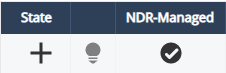
At this time the sensor entry is displayed in the Sensors table with these icons:
-
State - The icon "+" shows that the sensor entry was "Created".
-
Connected indicator (lightbulb) - Gray. It turns green when the sensor establishes the TLS tunnel to the NDR Indicator Management portal.
-
xNDR-Managed - The NDR application manages this Security Gateway.
-
-
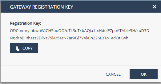
Select the sensor entry (highlighted in blue) and select Generate Registration Key from the Actions menu.
A new window opens with the registration key, for example:
-
Copy the registration key for use on the appliance.
Registering the Appliance
-
If the sensor requires an HTTPS proxy server to access the Internet:
-
Configure the proxy server in Gaia OS in the Gaia Portal or with Clish.
-
Run this command in Expert mode:
export HTTPS_PROXY=http://<proxy ip/name>:<proxy port>For example:
# export HTTPS_PROXY=http://local.proxy:8080
-
-
On the command line on the appliance, in the Expert mode, run this command with the "
<registration key>" obtained from the NDR Indicator Management application portal in step 10 in the above procedure:curl_cli -f -s -S --cacert $CPDIR/conf/ca-bundle.crt https://portal.now.checkpoint.com/static/install.sh | bash /dev/stdin --token <registration key> --monitor eth1 --monitor eth2-01
Note - Configure at minimum one interface in monitor-mode. In the example above, the two interfaces
eth1andeth2-01are set as monitor interfaces. -
The appliance reboots automatically and connects to NDR with the registration key.
-
On the NDR Indicator Management application portal, the connected lightbulb turns green. The State icon then starts to rotate, which indicates policy installation. Finally, the State icon appears as a check mark - which means it is Activated.
Accessing the Sensor's Gaia Portal
When an NDR-Managed sensor is activated and connected, it can be monitored and controlled only from the NDR Indicator Management application portal.
A user on the domain where the sensor is registered can see the sensor's resource consumption status (CPU, memory, disk).
Go to the MANAGEMENT > System Monitor tab.
For a user with a Domain Administrator role:
Go to MANAGEMENT > Sensors tab's Actions menu: OPEN GAIA PORTAL.
When you select the sensor and click this option it opens the appliance's WebUI in a new browser tab. The administrator can change interface mappings, see appliance status, and install Jumbo Hotfix![]() Software package installed on top of the current software version to fix a wrong or undesired behavior, and to add a new behavior. Accumulators.
Software package installed on top of the current software version to fix a wrong or undesired behavior, and to add a new behavior. Accumulators.
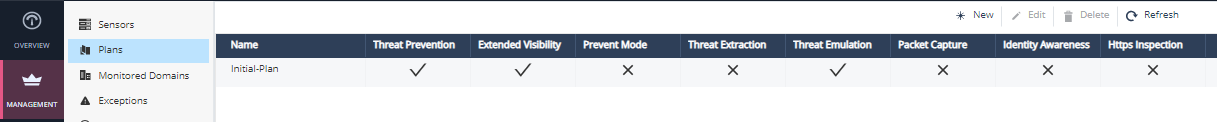
Plans
Each NDR sensor is related to a plan that controls its behavior. An Initial-Plan is automatically created for each domain and connected with all new sensors. You can change this plan, create more plans, and associate different sensors with the applicable one.
In contrast to standard Check Point Security Gateways that implement access control and threat prevention, NDR focuses only on the latter. The NDR does not manage an access policy – all traffic is allowed if it is not detected as malicious. This simplifies security management very much, allowing for plug-and-play operation. The plan is, therefore, quite simple, defining these attributes:
-
Threat Prevention – always enabled. It includes the IPS
Check Point Software Blade on a Security Gateway that inspects and analyzes packets and data for numerous types of risks (Intrusion Prevention System)., Anti-Virus Check Point Software Blade on a Security Gateway that uses real-time virus signatures and anomaly-based protections from ThreatCloud to detect and block malware at the Security Gateway before users are affected. Acronym: AV., and Anti-Bot Check Point Software Blade on a Security Gateway that blocks botnet behavior and communication to Command and Control (C&C) centers. Acronyms: AB, ABOT. blades. -
Extended Visibility – enabled by default. It includes the Application Control
Check Point Software Blade on a Security Gateway that allows granular control over specific web-enabled applications by using deep packet inspection. Acronym: APPI. and URL Filtering Check Point Software Blade on a Security Gateway that allows granular control over which web sites can be accessed by a given group of users, computers or networks. Acronym: URLF. blades. -
Prevent Mode – disabled by default (default is Detect Mode). Enabling Prevent Mode causes the sensor to block network traffic forwarded through the sensor's inline bridges if it is matched by one or more of the Threat Prevention blades with Medium or High confidence.
Note - An inline sensor blocks network traffic that match threat indicators with Preventaction, also when it is connected to a Detect Mode plan.
-
Threat Extraction – disabled by default, only active for inline traffic.
-
Threat Emulation
Check Point Software Blade on a Security Gateway that monitors the behavior of files in a sandbox to determine whether or not they are malicious. Acronym: TE. – enabled by default. NDR uploads files extracted from the network to the cloud for static and dynamic analysis (sandboxing). -
Packet Capture – disabled by default, packet captures are created and attached to log records for packets matching a threat prevention detection.
-
Identity Awareness and HTTPS Inspection – disabled by default and not editable. These settings show the status of the related services, which NDR cloud team provisions on request.
Example: