Moving From Detect to Prevent
Overview
NDR![]() Network Detection and Response blocks undesirable network traffic that bypassed other cyber defenses (presents as false negatives). The default operation mode is Detect, as most sensors are deployed passively with Monitor Mode interfaces. Prevent Mode on these sensors creates Prevent logs, but the traffic is not blocked as the sensor only inspects a mirror of the real network traffic.
Network Detection and Response blocks undesirable network traffic that bypassed other cyber defenses (presents as false negatives). The default operation mode is Detect, as most sensors are deployed passively with Monitor Mode interfaces. Prevent Mode on these sensors creates Prevent logs, but the traffic is not blocked as the sensor only inspects a mirror of the real network traffic.
This section details how to enable prevention based on NDR.
Prevention with Inline NDR Sensors
A physical NDR-Managed sensor deployed with inline interfaces prevents traffic flow through its bridged fail-open NICs.
To activate the inline sensor prevention:
-
Configure exceptions with action Prevent for protections that must apply even when in Detect Mode.
-
Edit the sensor's plan and enable Prevent Mode to set the default threat protection action to Prevent.
-
Set the action attribute for applicable threat indicators to Prevent.
|
|
Note - Prevention is not applied in these situations:
|

Determining what to block in Prevent Mode
To determine what to block, we recommend that you first review the traffic that is inspected in the default Detect Mode. Create exceptions to include any false positives that can influence business traffic.
For example, create a DOMAIN or PERSONAL view that matches such traffic:
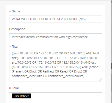
Note that the IP![]() Internet Protocol ranges in this example are the primary default internal ranges. Your network may have different internal IP ranges. You must configure these internal ranges in the MANAGEMENT > Settings tab, specifying the ranges in CIDR
Internet Protocol ranges in this example are the primary default internal ranges. Your network may have different internal IP ranges. You must configure these internal ranges in the MANAGEMENT > Settings tab, specifying the ranges in CIDR![]() Classless Inter-Domain Routing format. In addition, this example assumes that the NDR sensor's inline bridge forwards traffic between the internal network and the Internet (North/South) and ignores East/West traffic. Your network may have a different configuration.
Classless Inter-Domain Routing format. In addition, this example assumes that the NDR sensor's inline bridge forwards traffic between the internal network and the Internet (North/South) and ignores East/West traffic. Your network may have a different configuration.
In some cases, for example, when under active attack, you may prefer to switch to Prevent Mode immediately and create the exceptions only after users complain that their traffic is blocked.
Exceptions
Use the MANAGEMENT > Exceptions tab to manage Threat Prevention exceptions. You can apply the exceptions on specific sensors or globally on all domain sensors. Create Threat Prevention rules to configure exceptions, and install a Threat Prevention policy on the sensors for every modification.
The exception attributes are similar to the ones found in SmartConsole![]() Check Point GUI application used to manage a Check Point environment - configure Security Policies, configure devices, monitor products and events, install updates, and so on. application:
Check Point GUI application used to manage a Check Point environment - configure Security Policies, configure devices, monitor products and events, install updates, and so on. application:
-
Scope – Expressed as Sources or Destinations in CIDR notation. For an individual IP address, use /32.
-
Protections or Blades – Select blade names from the pull-down menu or enter a protection name.
-
Services – Select from the menu or enter the service name.
-
Action – Changes the behavior of the selected protections or blades for the defined scope and services:
-
Prevent – Used in Detect Mode or to enable Prevent on Low confidence protections.
-
Detect – Used in Prevent Mode to cause the sensor to log but not block the specified traffic.
-
Inactive – Turns off the selected protections or blades.
-
-
Track – Set to None when the action is Inactive.
Threat Prevention using Threat Indicators
For threat indicators managed on the INTEL tab you can select DETECT or PREVENT for the action. An NDR appliance uses Prevent to block network traffic with matching that are forwarded on its inline bridges. This block applies regardless if the plan is set to Detect or Prevent.
The indicators must be related to a data set that has Apply on NDR Sensors enabled (default). In addition, the indicators must be Enabled and not expired.
Threat indicators are the primary NDR response mechanism because they can be published to non-NDR-Managed Check Point Security Gateways and to 3rd party firewalls. This let you use NDR in a passive mode of operation and prevent threats indirectly.
You can manually create threat indicators from the NDR application user interface, load them from a file, or configure automated input feeds to pull them from external sources. In addition, NDR Behavioral Analytic AI![]() Artificial Intelligence engines automatically publish threat indicators to block detected high-risk traffic.
Artificial Intelligence engines automatically publish threat indicators to block detected high-risk traffic.
The default action for new manually-created indicators is DETECT. You can set the action to PREVENT during the initial entry or edit the indicators. You can edit individually or in bulk. For editing in bulk – select the indicators that you want to switch to PREVENT, select Bulk Edit, and set Action to Prevent. You can select the indicators and click PREVENT.
The default action is determined by the corresponding input feed's policy for automatically-created threat indicators. This policy applies only when the indicator value is first created. You can change the Action on existing indicators, and this new Action continues even if the input feed source refreshes the indicator.
For example, you can switch the Behavioral input feed action to Prevent for Medium and High confidence indicators. This input feed is created by default for all domains and represent the NDR Behavioral Analytic engines.
For more information on threat indicators, refer to the NDR Indicator Management User Guide.
Configuring Check Point Security Gateways to Pull NDR Indicators
You can easily configure your Check Point firewalls to pull feeds of threat indicators from NDR for blocking. It prevents threats automatically, with no need to policy push.
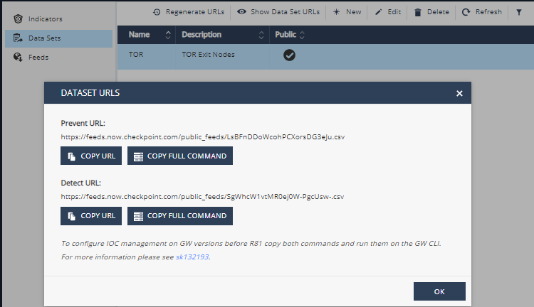
You can associate each indicator with one or more data sets, either manually or through the input feed policy. A data set is published on two output feed URLs: Prevent and Detect. Each of these feeds includes the indicators related to the data set that have the corresponding action (Prevent or Detect). This separation is useful because Check Point Security Gateways associate action with an individual feed configured on the Security Gateway![]() Dedicated Check Point server that runs Check Point software to inspect traffic and enforce Security Policies for connected network resources..
Dedicated Check Point server that runs Check Point software to inspect traffic and enforce Security Policies for connected network resources..
The URL![]() Uniform Resource Locator for each output feed is displayed on the portal and you can copy it to the clipboard with the COPY URL button. The COPY FULL COMMAND option runs the applicable "
Uniform Resource Locator for each output feed is displayed on the portal and you can copy it to the clipboard with the COPY URL button. The COPY FULL COMMAND option runs the applicable "ioc_feeds" command on a Security Gateway to pull the output feed.
To enable a feed on the Check Point Security Gateway:
-
Select the desired data set (for example, Behavioral or TOR Exit Nodes).
-
Click Show Data Set URLs.
-
Click COPY FULL COMMAND for the set of indicators (DETECT or PREVENT).
This puts the complete Security Gateway "
ioc_feeds" command to the clipboard buffer. -
Connect to the command line on the Security Gateway command line.
-
Log in to the Expert mode.
-
Paste and run the command.
Starting from R81.10 and higher, you can use the COPY URL option and configure the feeds from your SmartConsole. Go to Security Policies > Threat Prevention > Indicators.
For more information on how to enable this functionality on your Security Gateway, refer to sk132193.