Configuring the SD-WAN Device
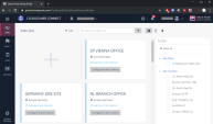
When you create the site at Check Point Harmony Connect, on this site you must configure your branch office to route traffic through Harmony Connect.
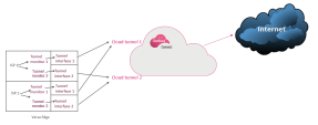
Check Point creates the back-end architecture for tunneling the traffic from the branch device to the Internet.
Example:
To configure your branch device:
-
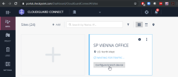
On the site thumbnail, click the Configure branch device button:
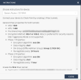
The Instructions window opens.
-
From the top field, select your SD-WAN branch office device.
-
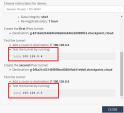
Follow the instructions on the screen to get the IPsec configuration properties, pre-shared key, tunnel addresses, and the traffic routes.
Example:

Best Practice - To enhance the service reliability Check Point recommends you to create and use two tunnels.
-
Click Close.
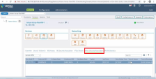
Configuring Versa on the Edge Device
You can route the incoming and outgoing traffic through IPsec tunnels from a Versa device to the Check Point Harmony Connect security service.
Through the IPsec you can enable Check Point security from your Versa management dashboard.
Steps to configure Versa SD-WAN:
Prerequisites
-
DNS Server
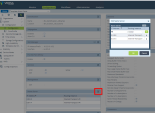
Check Point uses FQDN addresses for its cloud tunnels. To access the Check Point domains you must configure your Versa device to use DNS server.
To create FQDN Tunnels for integration with Versa:
-
Go to Other > System > Configuration > Configuration.
-
Add DNS servers to resolve these FQDN names.
Example:
Creating IPsec Check Point Tunnels
To establish connection through Check Point, you must attach the new CP-Tunnel tunnels to the SD-WAN on your Site.
Creating the First IPsec Check Point Tunnel

|
Note - A WAN IPsec Interface Name must have a suffix of _1. |
To create the first IPsec tunnel:
-
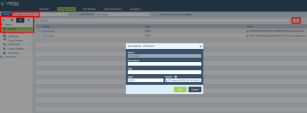
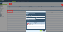
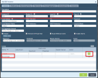
Go to Configuration page > Object tab > Address and click [+].
Example:
-
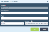
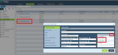
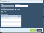
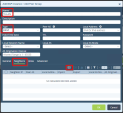
In the Edit Address window enter these parameters:
Name - CP-Tunnel1
Description (Optional)
Type - FQDN
FQDN - Enter the FQDN parameter configured on the Harmony Connect Site. SeeCreating a New Site .
Example:
-
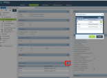
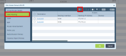
Go to Other > System > Configuration > Configuration and click Name Server.
Example:
-
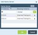
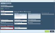
In the Edit Name Server window add the DNS servers to resolve these FQDN names.
Example:
-
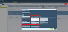
Create a new IPsec tunnel interface.
Creating the Second IPsec Check Point Tunnel

|
Note - A WAN Edge IPsec Interface name must have a suffix of _2. |
Repeat Steps 3-5 to create the second IPsec tunnel.
Name - Set to CP-Tunnel2.
Testing the IPsec Check Point Tunnels Configuration
To test the IPsec Check Point tunnels configuration perform these steps:
-
Add routes to both IPsec tunnels.
-
Set Site-to-Site IPsec VPN.
-
Bind the IPsec VPN to your Versa branch device.
-
Deploy changes.
-
Test your IPsec configuration
-
Go to Services > IPSEC > VPN Profiles.
On the General tab add two profiles that correspond to the two created IPsec tunnels.
Example:
-
Go to Services > IPSEC > VPN Profiles.
On the IKE tab:
-
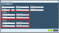
Make sure that Local Auth section has the IP Address.
-
Make sure that Peer Auth section has FQDN for Peer Auth.
Example:
-
-
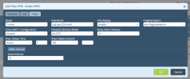
Go to Services > IPSEC > VPN Profiles.
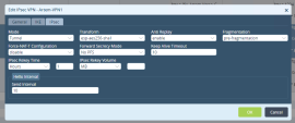
On the IKE tab set the value in the IKE Rekey Time field to 24 hours.
Example:

Note - Versa allows maximum 8 hours for IKE rekey. Check Point provides default 24 hours.
-
Click OK.
-
Click Save.
-
Commit the template to the Versa Orchestrator.
The changes are deployed immediately.
Creating a New Tunnel Monitoring Interface
Check Point provides two IPsec tunnels for redundancy and non-stop operation. When one of the Check Point tunnels is down for maintenance, Versa switches to the next Check Point tunnel. The usual switch takes several minutes. The pre-configured Tunnel Monitoring Interfaces for each tunnel ensure Versa a very quick switch (within 5 seconds). It ensures s reliable experience for the end user and an uptime of 99.999%.
Versa Tunnel Monitor Interfaces use test IP addresses that Check Point provides. See the site instructions on the Infinity Portal.
Versa Tunnel Monitor Interfaces connect to the Versa IPsec tunnel interfaces over BGP.
Example:
To configure Versa Monitoring interfaces:
-
Create new Tunnel Monitoring interfaces.
-
Connect the new Versa Monitoring Interfaces to the Versa Tunnel Interfaces.
- Go to Networking > Interfaces > Tunnel.
-
In the Edit Tunnel Interface window create two IPsec tunnels.
Each of these tunnels must have its own unique private IP subnet (for example, 10.0.1.0/24 and 10.0.2.0/24).
Example:
-
Click OK.
-
Click Add to create two tunnels.
In the Add Tunnel Interface window specify these parameters for the pairs:
-
For Interface tvi-0/201 - Set Paired Interface tvi-0/202
-
For Interface tvi-301 - Set Paired Interface tvi-302
The tunnel pair is created automatically.
Example for Interface tvi-0/201:
Example for Interface 301 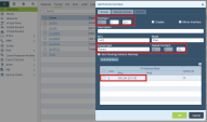
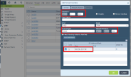
-
-
Click OK.
-
Edit the automatically created tunnels tvi-0/202 and tvi-302:
-
In the Interfaces table, click Edit for each paired tunnel.
-
In the Edit Tunnel Interface window set these parameters for the pairs:
-
For Interface tvi-0/202 - Set Paired Interface tvi-0/201
-
For Interface tvi-302 - Set Paired Interface tvi-301
-
Example for Interface tvi-0/202:
Example for Interface tvi-0/302: 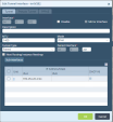
-
The Interfaces table with all the paired tunnels configured (example):
Versa Tunnel Monitor Interfaces connect to the Versa IPsec tunnel interfaces over BGP. For more information see Creating a New Tunnel Monitoring Interface.
To connect Versa Monitoring Interfaces to Versa Tunnel Interfaces:
-
Create BGP Instance on Versa Monitoring Interfaces.
-
Create BGP Instance on Versa Tunnel Interfaces.
-
Set up route between these two BGP instances through mutual Peer Groups.
To create a BGP instance on Versa Monitoring Interfaces:
-
Go to Networking > Virtual Routers.
-
Create three LAN routes:
-
tvi-0/302.0 - Additional LAN interface compatible with Paired Interfaces tvi-301/302
-
tvi-0/202.0 - Additional LAN interface compatible with Paired Interface tvi-201/202
-
tvi-0/603.0 - LAN Route
-
-
Click on the LAN Route in the table to see the virtual route details.
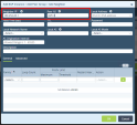
In the Edit window click on Virtual Router Details > Interface Networks.
-
Click OK.
Example:
-
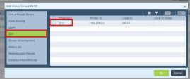
In the Edit window click on BGP.
In the Instance ID click on the first row.
Example:
-
Click OK.
-
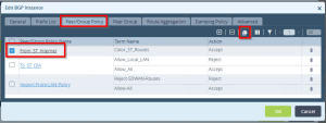
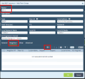
In the Edit BGP Instance window click on Peer / Group policy tab, select From_ST_Internet_Policy.
To create a BGP instance on Versa Tunnel Interfaces
-
Click [book] icon to clone the created policy.
Example:
-
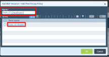
In the Add BGP Instance window enter a name for this new policy:
Name- Set to From_ST_CheckPoint1
-
Click on the Color ST Routes and enter this name in the Name filed:
Name- Set to From_ST_CheckPoint1
Example:
-
Click OK.
-
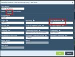
On Action tab set Local Preference to a higher priority number. In this example it is set to 130.

Note - The number priority ranges in direct relationship to its value.
-
Click OK.
Example:
-
-
Repeat Step 8 to create the second clone for this policy.
-
Name- Set to From_ST_CheckPoint2
-
Local Preference - Set to 125 (a lower priority number).
-
-
Click OK.
Created BGP connections in the BGP Instance table (example):
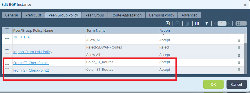
To set up a route from Versa Monitoring Interfaces to Versa Tunnel Interfaces:
-
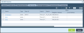
Go to Edit BGP Instance > Peer Group tab.
-
Click [+] to add and configure three groups based on groups created before:
-
ST-Group-1 - based on From_ST_Internet_Policy
-
CP-1 - based on From_ST_CheckPoint1
-
CP-2 - based on From_ST_CheckPoint2
 To configure three Peer Groups
-
Go to Peer Group > Edit BPG Instance and click [+].
-
In the Add Peer Group window enter these parameters:
Name - Set CP-1 / CP-2 / ST-Group-1
Type - Set EBGP
Example:
-
In Neighbors tab - Add Neighbor IP and Peer AS.
Example:
-
In Advanced tab - Add Import and select these options:
Created Peer Groups (example):
-
-
Configure routes between the Versa.
 Procedure
-
Go to Edit CheckPoint-1 > Virtual Router Details.
-
Set Instance Name to CheckPoint-1.
-
Click OK.
Repeat Steps a-c for the second route. Set Set Instance Name to CheckPoint-2.
-
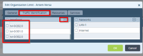
Go to Other >Organization > Limits and open template.
-
Add to Traffic identification all the interfaces and resources created before.
Example:
-
Click OK.
-
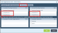
Click Resources:
Example:
-
Click OK.
Go to Networking > IP-SLA > Monitor and create 2 monitors: Monitor-1 and Monitor-2. Click OK.
-
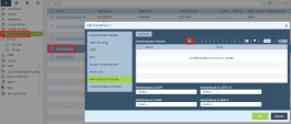
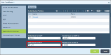
Go back to Virtual routes. Open first route, create Redistribution policy (To LAN) and add Monitor to it.
Redistribution Policy Name - Set to TO-LAN
Example:
-
Click [+].
-
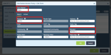
In Edit Term window enter Term Name (Static), Protocol
(Static) and Monitor(1 or 2).
Example:
-
Go to Redistribution Policy > Redistribute to BGP field and enter the TO-LAN name.
Example:
-
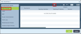
Go to Static Route and click [+] to add a new route.
Example:
-
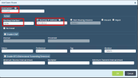
In the Add Static Route window in the Destination field enter: 0.0.0.0/0.
Example:
-
-
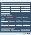
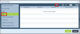
Go to BGP and click [+] to add a new BGP Instance.
Example:
-
Enter the Instance parameters:
-
Instance ID
-
Local ID
-
Local AS
Example:
-
-
Go to Peer Group tab and click [+] to add a new Peer group.
-
In the Peer Group window:
-
Enter these parameters:
-
Name - Set to TO-LAN
-
Type - Set to EBGP
-
-
Add Neighbors.
Example:
-
-
Click OK.
-
Repeat Step 3 to edit the CheckPoint-2 group and add Monitor-2.
-
Go to Services > IPSEC > VPN Profiles.
-
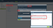
Add the Checkpoint-1 and Checkpoint-2 profiles that correspond to the IPsec tunnels.
Example:
-
Go to Workflows > Devices and open your device.
-
Open the Bind data tab.
-
Open your Device.
To the IPsec section of your device add the IP of your created interface that is applicable for the IPsec tunnel.
Example:
-
Click OK.
-
Redeploy the changes and commit the template.
Repeat the procedure in Setting Site-to-Site IPsec VPN.
You completed the configuration of the tunnels, added them to the Harmony Connect, and routed the traffic through them.
Testing your Configuration
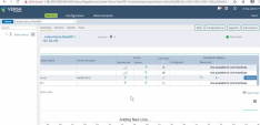
To make sure that the traffic from your Versa SD-WAN device passes to the Internet through the Check Point Harmony Connect system, you must check its activity on your branch device.
After that go to the Check Point Infinity Portal and watch the Cybersecurity Events.
To test the Versa configuration on your device:
-
Connect to the Internet from a computer behind your edge device and browse sites.
-
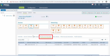
From Versa Console go to Monitor > Edges.
-
Click on the Edge that sends the traffic.
-
Locate your Check Point tunnels and make sure that they are up.
To test the Versa configuration from the Infinity Portal:
-
Log into the Check Point Infinity Portal.
-
Go to Harmony Connect > Sites and locate your Site.
-
Click Menu > Show Instructions and locate the applicable Test IP address.
-
Use
pingfor the Test IP address to test this configuration.Example:
You can watch the Cybersecurity Events at the Check Point Infinity Portal. See Monitoring Cybersecurity Events.

