Configuring Fortinet SD-WAN
Prerequisite
Fortinet account.
Procedure
-
Sign into the Fortinet Administrator Portal.
-
Go to VPN > IPsec Tunnels.
-
Select Create New > IPsec Tunnel.
-
Set Template type to Custom.
-
In the Name field, enter a name for the VPN tunnel.

Note - The tunnel name cannot include any spaces or exceed 13 characters.
For example: TO_Cloud_Prim
-
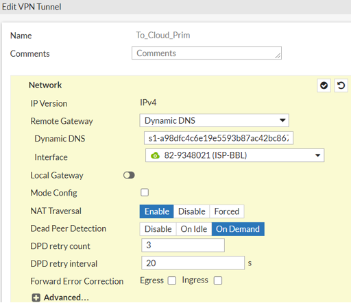
To set the network settings:
-
From the Remote Gateway drop-down list, select Dynamic DNS.
-
In the Dynamic DNS field, enter the FQDN from the Harmony Connect Portal.
For example: s1-a98dfc4c6e19e5593b87ac42bc8672df.checkpoint.cloud.
-
From the Interface drop-down list, select an incoming interface to wan1.
-
-
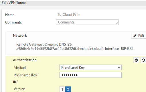
Under Authentication:
-
From the Method drop-down list, select Pre-shared Key.
-
In the Pre-shared key field, enter the key value from the Harmony Connect Portal.
-
Under IKE, set Version as 2.
-
-
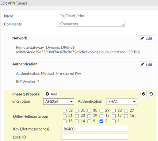
Under Phase 1 Proposal:
-
From the Encryption drop-down list, select AES256.
-
From the Authentication drop-down list, select SHA1.
-
Set Diffie-Hellman Group as 2.
-
In the Key Lifetime (seconds), enter 86400.
-
-
Under Phase 2 Selectors:
-
In Local Address field, enter the local IP/Network.
For Example: 172.18.30.0/255.255.255.0.
-
In Remote Address field, enter 0.0.0.0/0.0.0.0.
-
-
Under Phase 2 Proposal:
-
From the Encryption drop-down list, select AES256.
-
From the Authentication drop-down list, select SHA1.
-
Set Enable Replay Detection, Local Port, Remote Port, and Protocol checkboxes as All.
-
Enable Auto-negotiate checkbox.
-
From the Key Lifetime drop-down list, select Seconds.
-
In the Seconds field, enter 3600.

-
-
Select OK.
-
Repeat the steps to create the second tunnel.
-
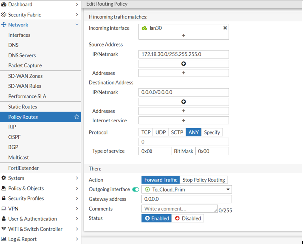
Go to Network > Policy Routes and select Policy Route.
-
In the Incoming interface, select Vlan/Lan.
For example: lan30.
-
Under Source Address, enter the IP/Network.
For example: 172.18.30.0/255.255.255.0.
-
Under Destination Address, enter the IP/Network value as 0.0.0.0/0.0.0.0.
-
Set Protocol as Any.
-
Under Then, set Action as Forward Traffic.
-
Enable Outgoing interface and select the first VPN Tunnel.
For example: TO_Cloud_Prim.
-
In the Gateway address, enter the value 0.0.0.0.
-
Set Status as Enabled.
-
Select OK.
-
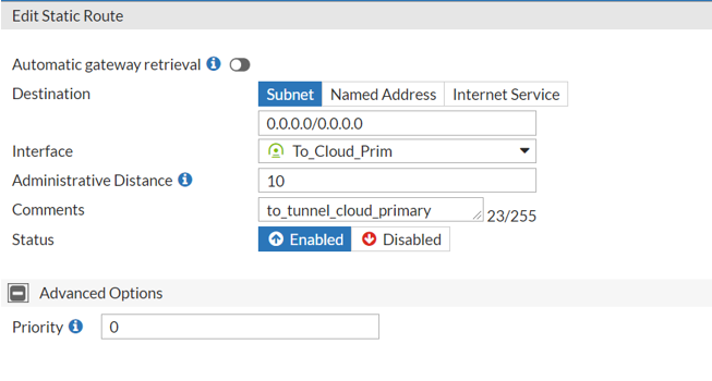
Go to Network > Static Routes and select Static Route.
-
Set the Destination as Subnet.
-
From the Interface drop-down list, select the first VPN tunnel.
For example: To_Cloud_Prim
-
Set the Status as Enabled.
-
Select OK.
-
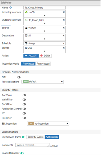
Go to Policy & Objects > Firewall Policy and select New Policy.
-
In the Name field, enter a policy name.
For example To_Cloud_Primary
-
In Incoming Interface, select Vlan/Lan.
For example lan30.
-
In Outgoing interface, select the first VPN tunnel.
For example To_Cloud_Prim.
-
In Source, select the network address.
For example: Vlan30.
-
Set the Destination as All.
-
Set Schedule as Always.
-
Set Service as ALL.
-
Set Action as Accept.
-
Disable NAT.
-
Enable Log Allowed Traffic and select All Sessions.
-
Select Enable this policy.
-
Select OK.