Configuring Cisco vManage on the SD-WAN Device
Refer to the Cisco SD-WAN vManage Help for more information.
To configure Cisco vManage on your SD-WAN Device, perform these steps:
A WAN Edge IPSec Interface Feature Template Name must have a suffix of IPSec1.
To create a WAN Edge IPSec Interface Feature Template for the first tunnel:
-
Go to Configuration > Templates > Feature Templates.
Example:
-
Click the VPN Interface IPsec (WAN)
Example:
-
Configure the template:
-
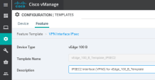
Template Name and Description
Example:
-
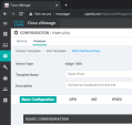
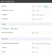
In the Basic Configuration section, configure your WAN interface as your IPsec Source Interface:
Example:
Field Settings Shutdown
Select the Global scope and select No to enable the interface.
Interface Name (1..255)
Select the Global scope and enter:
ipsec1Description
Select the Global scope and enter a description of the IPsec interface.
IPv4 address
Select the Global scope and enter the IPv4 address of the IPsec interface.
-
The format is:
ipv4-prefix/length -
The IPv4 address must be a /30
Source
Select Interface.
IPsec Source Interface
Select the Global scope and enter the name of the physical interface that is the source of the IPsec tunnel.
This interface must be configured in VPN 0.
IPsec Destination IP Address/FQDN
Select the Global scope and enter the destination of the IPsec tunnel that IKE key exchange uses.
Enter either an IPv4 address or the fully qualified DNS name that points to the destination.
TCP MSS
Do not change the default value.
IP MTU
Do not change the default value.
-

Note - Do not change the values in the Dead-Peer Detection section.
-
-
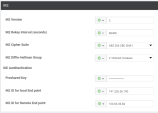
In the IKE section:
-
In the IKE ID for local End point field, enter the public IP address of the WAN interface configured as your IPsec Source Interface.
-
In the IKE ID for Remote End point field, enter the private (internal) IP address of the primary / first gateway.

Note - This name must differ from its resolved FQDN.
Example:
Field Settings IKE Version
Select the Global scope and enter
2.IKE Rekey interval (seconds)
Select the Global scope and enter
86400.IKE Cipher Suite
Select the Global scope and select AES 256 CBC SHA1.
IKE Diffie-Hellman Group
Select the Global scope and select 2 1024-bit modulus.
Preshared Key
Select the Global scope and enter the password to use with the preshared key.
IKE ID for local End point
Select the Global scope and enter a local end point identifier.
Range: 1 through 64 characters
Default: Tunnel source IP address
IKE ID for Remote End point
Select the Global scope and enter a remote end point identifier.
Range: 1 through 64 characters
Default: Tunnel's destination IP address
-
-
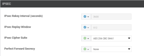
In the IPSec section, configure these settings.
Example:
Field Settings IPsec Rekey Interval
Do not change the default value.
IKE Replay Window
Do not change the default value.
IKE Cipher Suite
Select the Global scope and select AES 256 CBC SHA1.
Perfect Forward Secrecy
Select the Global scope and select None.
-
Click Save at the bottom.
Another WAN Edge IPSec Interface Feature Template Name must have a suffix of IPSec2.
You can copy the first WAN Edge IPsec Interface Feature Template you just created and use it for the second (redundant) IPsec interface.
To create a WAN Edge IPsec Interface Feature Template for the second Tunnel:
-
Go to Configuration > Templates > Feature Templates.
-
Copy the IPsec Interface template you created in the section before:
-
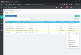
Select the template
-
On the right, click the ... and click Copy
Example:
-
-
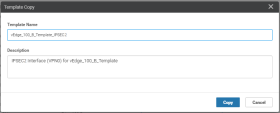
In the Template Copy window:
-
Change the Template Name suffix to IPSec2.
-
Change the Description to IPSec2.
Example:
-
-
Click Copy to save the Template.
-
 Update the parameters of the Secondary IPsec Tunnel.

Note - Change only the specified parameters. Leave all other information set to default.
To update the data for the IPSec2 Tunnel:
-
Edit to the IPSec2 Template.
-
Select the template
-
On the right, click the ... and click Edit
-
-
Configure the template:
-
The Template Name and Description parameters:
-
Change the Template Name suffix to IPSec2.
-
Change the Description to IPSec2.
-
-
Field Settings Shutdown
Select the Global scope and select No to enable the interface
Interface Name (1..255)
Select the Global scope and enter:
ipsec2Description
Select the Global scope and enter a description of the IPsec interface.
IPv4 address
Select the Global scope and enter the IPv4 address of the IPsec interface.
The format is:
ipv4-prefix/lengthThe IPv4 address must be a /30.
Source
Select Interface.
IPsec Source Interface
Select the Global scope and enter the name of the physical interface that is the source of the IPsec tunnel.
You must configure this interface in VPN 0.
IPsec Destination IP Address/FQDN
Select the Global scope and enter the destination of the IPsec tunnel that IKE key exchange uses.
Enter either an IPv4 address or the fully qualified DNS name that points to the destination.
TCP MSS
Do not change the current value.
IP MTU
Do not change the current value.
-
Field Settings IKE Version
Select the Global scope and enter
2.IKE Rekey interval (seconds)
Select the Global scope and enter
86400.IKE Cipher Suite
Select the Global scope and select AES 256 CBC SHA1.
IKE Diffie-Hellman Group
Select the Global scope and select 2 1024-bit modulus.
Preshared Key
Select the Global scope and enter the password to use with the preshared key.
IKE ID for local End point
Select the Global scope and enter a local end point identifier.
Range: 1 through 64 characters
Default: Tunnel's source IP address
IKE ID for Remote End point
Select the Global scope and enter a remote end point identifier.
Range: 1 through 64 characters
Default: Tunnel's destination IP address
-
-
Click Save at the bottom.
-
-
Save the IPSec2 Template.
Configure your branch device with the two new IPsec Templates forIPsec1 and IPsec2 interfaces. You must edit the device template and add both interfaces to the VPN0 section.
To configure your branch device:
-
Edit the Template:
-
Click Configuration Template > Configuration > Templates.
-
Select the Device.
-
On the right side click ... and click Edit.
Example:
-
-
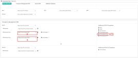
In the Transport & Management VPN section > Additional VPN 0 Templates section, click VPN Interface IPsec.
In the two VPN Interface IPsec fields select the Feature Templates of the IPSecC1 and IPSec2 Interfaces you created in the earlier steps.
Example:
-
vEdge_100_B_Template_IPSEC1
-
vEdge_100_B_Template_IPSEC2
Example:
-
-
Click Update to save changes to the device template.
Complete your CloudGuard Connect configuration and remove any other conflicting routes. You must edit the VPN 1 (LAN) Template.
To add routing from the LAN towards the IPsec Tunnels:
-
Edit the Template:
-
Click Configuration Template > Configuration > Templates.
-
Select the Device.
-
On the right, click ... and click Edit.
Example:
-
-
On the VPN 1 Template Tab:
-
Click the IPV4 Route tab and delete the default route, where applicable:
Example:
-
Configure the default IPSec Route to IPSec1 and IPSec2:
-
You completed the configuration of the tunnels, added them to the CloudGuard Connect, and routed the traffic through them.
To test the CloudGuard configuration, you must check its activity on your branch device.
After that go to the Check PointInfinity Portal and watch the Cybersecurity Events.
-
Testing Configuration from the Cisco SD-WAN User Interface
To test the CloudGuard configuration:
- Testing Configuration through the SSH Terminal
You can watch the Cybersecurity Events at the Check Point Infinity Portal. See Monitoring Cybersecurity Events.


