Configure Intra-VCN and VCN Gateway Ingress Routing for Cloud Firewall for Oracle Cloud (OCI)
In 2022, Oracle Cloud![]() Oracle Cloud is a cloud computing service offered by Oracle Corporation. It provides servers, storage, networks, applications, and services through a global network of Oracle Corporation-managed data centers. Infrastructure introduced a set of routing enhancements that significantly expand traffic control capabilities within and into Virtual Cloud Networks (VCNs). The three key additions are:
Oracle Cloud is a cloud computing service offered by Oracle Corporation. It provides servers, storage, networks, applications, and services through a global network of Oracle Corporation-managed data centers. Infrastructure introduced a set of routing enhancements that significantly expand traffic control capabilities within and into Virtual Cloud Networks (VCNs). The three key additions are:
-
Intra-VCN Routing - Allows administrators to define explicit routes for traffic flowing between subnets within the same VCN, rather than relying on default local routing.
-
Internet and NAT Gateway Ingress Routing - Enables route control for inbound public traffic entering a VCN through an Internet Gateway or NAT Gateway.
-
Service Gateway Ingress Routing - Allows traffic from OCI services, arriving via a Service Gateway, to be directed to specific destinations inside a VCN.
These enhancements make it possible to deploy Check Point Cloud Firewall in a simpler, more scalable architecture — with full inspection of both intra-VCN (east-west) and ingress (north-south) traffic flows - without relying on the legacy VCN direct local routing model.
For the official Oracle announcement, refer to the Oracle Cloud Infrastructure blog.
Supported Use Case
This guide covers a single-hub topology that serves as a flexible baseline for a wide range of deployment configurations. The hub-and-spoke model places a Cloud Firewall cluster![]() Two or more Security Gateways that work together in a redundant configuration - High Availability, or Load Sharing. at the center of all traffic flows, enforcing security policy
Two or more Security Gateways that work together in a redundant configuration - High Availability, or Load Sharing. at the center of all traffic flows, enforcing security policy![]() Collection of rules that control network traffic and enforce organization guidelines for data protection and access to resources with packet inspection. for both internal subnet-to-subnet traffic and traffic entering the environment from the Internet or OCI services.
Collection of rules that control network traffic and enforce organization guidelines for data protection and access to resources with packet inspection. for both internal subnet-to-subnet traffic and traffic entering the environment from the Internet or OCI services.
Prerequisites
Before proceeding, make sure the following are in place:
-
An active Oracle Cloud Infrastructure account. If you do not have one, register at the Oracle Cloud sign-up page.
-
A functioning Intra-VCN network topology, configured as described in the topology section below.
-
A Check Point Cloud Firewall cluster deployed in the Hub (Security) VCN. Cloud Firewall solution is available through the Oracle Cloud Marketplace.
-
Linux VM instances running in their respective subnets, as defined by the use-case topology.
|
|
Note - In production environments, deploy Cloud Firewall instances in a High Availability (HA) cluster configuration. |

Reference Topology
Refer to this topology diagram for a visual representation of the subnet layout, VCN structure, DRG attachments, and traffic flow paths described in the configuration steps below:

Configuration
This section covers the minimum required configuration to establish Cloud Firewall-based inspection for intra-VCN and ingress traffic on OCI.
-
VCN and Subnet Layout
Create the following subnets within the Security/DMZ VCN and the Internal VCN. In the OCI Console, navigate to Virtual Cloud Networks > Virtual Cloud Network Details to create and manage subnets.
-
Security VCN -
10.100.0.0/16:-
Frontend Subnet -
10.100.0.0/24 -
Backend Subnet -
10.100.1.0/24 -
DMZ Subnet -
10.100.2.0/24
-
-
Internal VCN -
10.10.0.0/16:-
Web Subnet -
10.10.0.0/24 -
Database Subnet -
10.10.1.0/24
-
Then deploy the Cloud Firewall instances with network interfaces attached to the Frontend and Backend subnets.
-
-
Cloud Firewall Gateway Configuration
Deploy the Cloud Firewall cluster by following the instructions in the Deploying a Check Point Cluster in Oracle Cloud Infrastructure chapter.
After deployment, add the following static routes on each cluster member
 Security Gateway that is part of a cluster.:
Destination
Next Hop
0.0.0.0/0(Default)10.100.0.110.100.0.0/1610.100.1.110.100.2.0/2410.100.1.1 -
Network Load Balancer
-
Before creating the load balancer, deploy a server instance in the Web Subnet of the Internal VCN and note its private IP address.

-
Then configure the Network Load Balancer (NLB) as follows:
-
In the OCI Console, create a Network Load Balancer, selecting the Security VCN and the DMZ Subnet for networking.

-
Create a Listener with protocol TCP and port 8080.

-
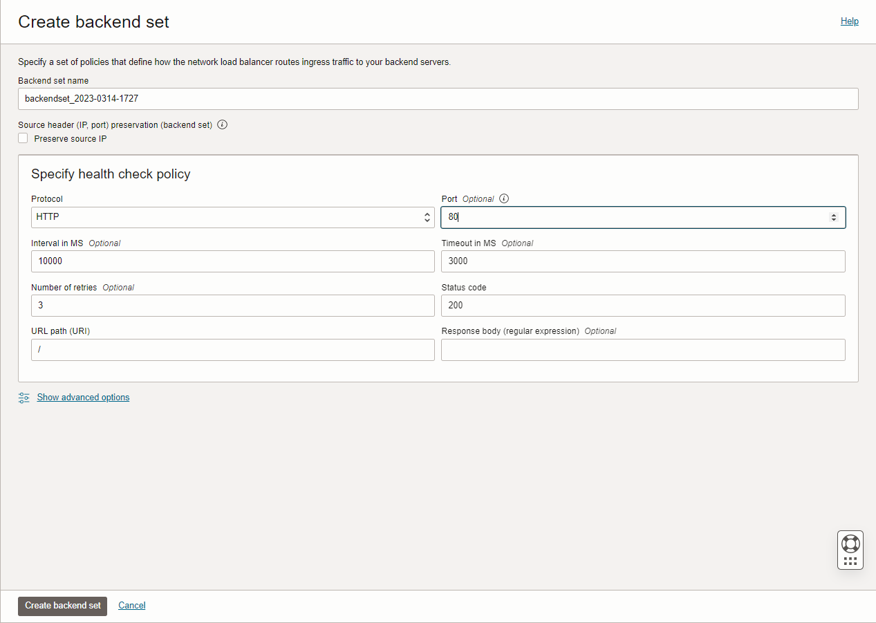
Create a Backend Set with a health check policy targeting port 80 on the server instance created above. Do not add any backends at this stage.
-
-
After the NLB is provisioned, navigate to the existing Backend Set, click Edit, and set the load balancing policy to 5-Tuple Hash. The Preserve Source IP option does not need to be enabled.

-
Save the changes, then click Add Backends. Select IP Addresses (not Compute Instances), enter the server's private IP address, and set the backend port to 80.

-
-
Dynamic Routing Gateway (DRG)
Create a DRG and attach it to both VCNs using the following attachment configuration:
Attachment Name
VCN
DRG Route Table
VCN Route Type
sec-drg-attSecurity FromFirewall Subnet CIDRs serv-drg-attServers 2Firewall VCN CIDRs DRG Route Table — FromFirewall (for sec-drg-att):
Destination CIDR
Next Hop Attachment Type
Next Hop Attachment Name
10.10.0.0/16Virtual Cloud Network sec-drg-attVCN Route Table — rt-to-FW (associated with sec-drg-att):
Destination
Target Type
Target
Route Type
0.0.0.0/0Private IP 10.100.1.4Static DRG Route Table — 2Firewall (for serv-drg-att):
Destination CIDR
Next Hop Attachment Type
Next Hop Attachment Name
0.0.0.0/0Virtual Cloud Network sec-drg-attNo VCN Route Table is required for
serv-drg-att. Do not enable route redistribution on this attachment. -
VCN Route Tables
-
Security VCN
Default Route Table for Security VCN:
Destination
Target Type
Target
Route Type
0.0.0.0/0Internet Gateway sec-IGWStatic 10.0.0.0/8Private IP 10.100.0.4Static Route Table — backend-default:
Destination
Target Type
Target
Route Type
0.0.0.0/0Private IP 10.100.1.4Static 10.0.0.0/8Dynamic Routing Gateway mydrgStatic Route Table — ingressRT:
Destination
Target Type
Target
Route Type
10.100.2.0/24Private IP 10.100.0.4Static Route Table — DMZ_RT:
Destination
Target Type
Target
Route Type
0.0.0.0/0Private IP 10.100.1.4Static Route Table — VCN-Ingress:
-
Destination
Target Type
Target
Route Type
0.0.0.0/0Internet Gateway sec-IGWStatic 10.10.0.0/16Private IP 10.100.0.4Static 10.100.0.0/16Private IP
10.100.0.4Static
-
Servers VCN
Default Route Table for Servers VCN:
Destination
Target Type
Target
Route Type
0.0.0.0/0Dynamic Routing Gateway mydrgStatic
-
-
Security Policy Configuration
NAT Rules
Create the following network objects and associated NAT rules in SmartConsole
Check Point GUI application used to manage a Check Point environment - configure Security Policies, configure devices, monitor products and events, install updates, and so on.:Network Name
Address / Mask
NAT Type
Translated Address
Servers 10.10.0.0 / 255.255.255.0Hide 10.100.1.4Frontend 10.100.0.0 / 255.255.255.0Hide Gateway Backend
10.100.1.0 / 255.255.255.0Hide
Gateway
DMZ
10.100.2.0 / 255.255.255.0Hide
10.100.1.4Gateway Topology
-
Create a Network Group object containing the following networks:
-
Frontend

-
Servers

-
DMZ

-
Backend

-
-
In the Gateway Object, set the topology for
eth1to the Network Group created above.
-
Set the topology for
eth0to External.
Access Control Policy

-
Define rules specifying the appropriate destination hosts or networks in the Destination column.
-
Ensure a Cleanup Rule is in place with an action of Drop for all unmatched traffic.
-
Enable logging on relevant rules to facilitate troubleshooting and visibility.
-