Deploying a Check Point Cluster in Oracle Cloud Infrastructure
Known Limitations
-
You must configure NTP on the environment for failover to work correctly. For more information, see the Oracle API requirements.
-
To inspect East/West traffic, each Backend subnet that requires inspection must exist in its own VCN and be routed to the Backend VNIC via LPGs or DRG.
Method of Operation
In a traditional Check Point Cluster![]() Two or more Security Gateways that work together in a redundant configuration - High Availability, or Load Sharing., Cluster members use multicast or broadcast for state synchronization and health checks. However, Oracle Cloud
Two or more Security Gateways that work together in a redundant configuration - High Availability, or Load Sharing., Cluster members use multicast or broadcast for state synchronization and health checks. However, Oracle Cloud![]() Oracle Cloud is a cloud computing service offered by Oracle Corporation. It provides servers, storage, networks, applications, and services through a global network of Oracle Corporation-managed data centers. Infrastructure (OCI) does not support multicast and broadcast, so Check Point Cluster members communicate over unicast.
Oracle Cloud is a cloud computing service offered by Oracle Corporation. It provides servers, storage, networks, applications, and services through a global network of Oracle Corporation-managed data centers. Infrastructure (OCI) does not support multicast and broadcast, so Check Point Cluster members communicate over unicast.
Additionally, a regular ClusterXL in High Availability mode uses Gratuitous ARP to announce the Active member's MAC address associated with the Virtual IP during normal operation and failover. In contrast, OCI leverages API calls.
When an Active OCI Cluster member![]() Security Gateway that is part of a cluster. fails, the Standby member takes over by:
Security Gateway that is part of a cluster. fails, the Standby member takes over by:
-
Associating the cluster's Private and Public Secondary IP addresses to the Primary vNIC
 Virtual Network Interface Card. Software-based abstraction of a physical interface that supplies network connectivity for Virtual Machines.
 -
Associating each Secondary Public/Private IP address pair on the Primary vNIC for every published service
-
Associating the Secondary Private IP address to the Secondary vNIC
This process allows the new Active Cluster member to take ownership of the cluster resources without using Gratuitous ARP in the OCI environment.
Oracle API Authentication
For the Cluster members to make API calls to Oracle automatically, they must have permissions to perform those API calls within the target compartment. This is accomplished through Oracle Identity Manager.
This guide covers how to:
-
Create a Dynamic Group with a rule
Set of traffic parameters and other conditions in a Rule Base (Security Policy) that cause specified actions to be taken for a communication session. that identifies only the Cluster Members to include in the group. -
Create a policy that grants the required permissions to the defined Dynamic Group.
By following these steps, the correct Cluster members get the necessary privileges to make Oracle API calls for automating failover and other cluster operations.
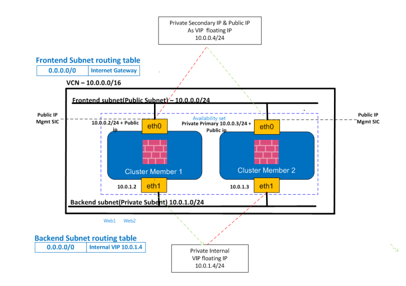
Solution Topology
This sample environment is used to explain the configuration steps. When implementing these steps in your own environment, be sure to substitute the IP addresses used in the examples with the actual IP addresses relevant to your specific setup.
CloudGuard Cluster Deployment
Follow these instructions to deploy the Check Point's CloudGuard Cluster solution in Oracle. Perform the steps from the Oracle portal in the preferred compartment(s).
-
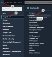
Sign in to your OCI tenant account.
-
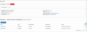
Select the relevant CloudGuard listing from the Oracle Cloud Marketplace.
-
Create a new VCN or select an existing VCN (for example, VCN with CIDR Block 10.0.0.0/16).

-
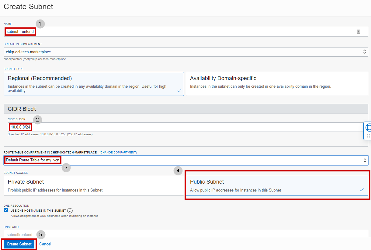
Add two subnets to your VCN: one public subnet and one private subnet.
-
Frontend public subnet (Ex. - 10.0.0.0/24)
-
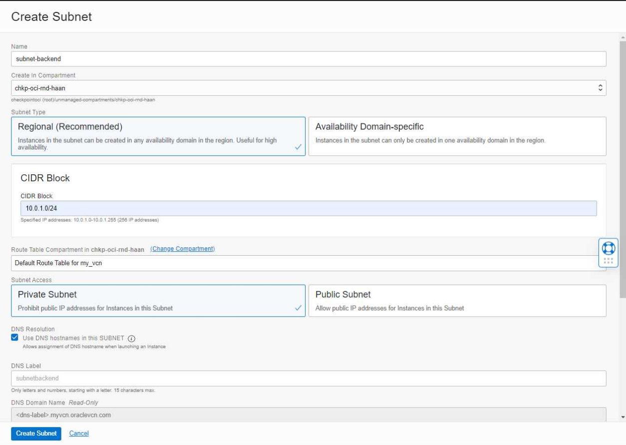
Backend private subnet (Ex. - 10.0.1.0/24)
Optional: You can place each subnet in its own independent VCN. In this scenario, the VCN CIDR contains only one subnet which is the entire VCN CIDR.
Example: VCN defined as 10.1.0.0/24 has one subnet that also uses 10.1.0.0/24

-
-
Create a public subnet: for example, Frontend (CIDR Block 10.0.0.0/24).
Optional: The Frontend subnet can also be private. In this case, you must set the default route for the Frontend subnet to use a Target Type of Service Gateway and a Destination Service of All <Region> Oracle Services in Oracle Services Network for the API calls to succeed.
-
Create a private subnet: for example, Backend (CIDR Block 10.0.1.0/24).
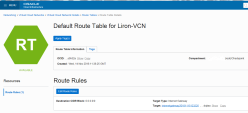
Final VCN configuration with two subnets: Frontend and Backend.
-
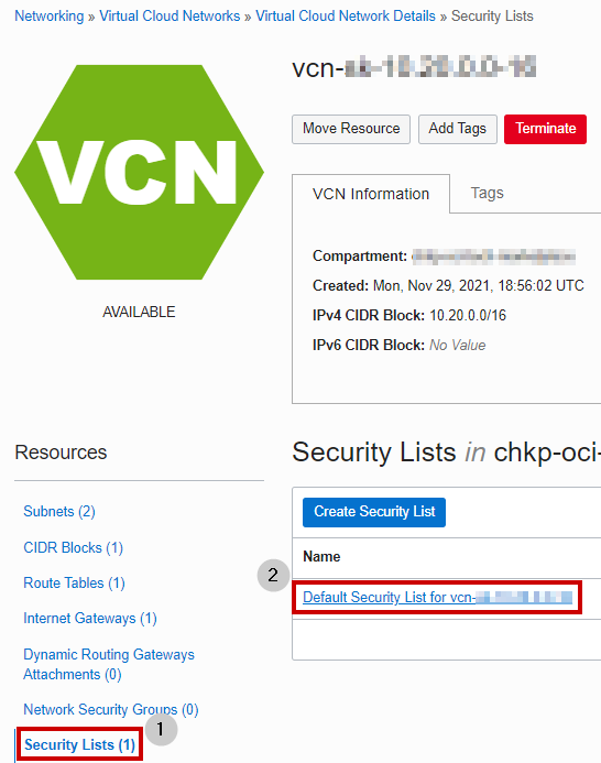
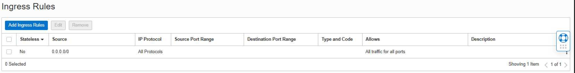
Configure your VCN's Security List to allow all traffic on all protocols. This lets Check Point control and monitor all traffic.


-
Create both CloudGuard Cluster members.
By default, the Primary vNIC on each instance is attached to the Frontend subnet.
-
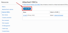
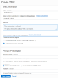
Add a Secondary vNIC to each Cluster member.


Notes:
-
Connect the Primary vNIC to the Frontend subnet; Connect the Secondary vNIC to the Backend subnet.
-
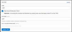
You must ensure both vNICs of each Cluster member are configured with the check box for Skip source/destination check.
-
-
Select one of the Cluster members and add a new Secondary Private IP address to the Primary vNIC.
-
Create a reserve Public IP address and attach it to the Secondary Private IP address you created in step 10. This represents the cluster IP address.
-
Create one more Secondary private IP and attach it to the member's Secondary vNIC of the slected member from step 10 (secondary VIP for outbound traffic).
-
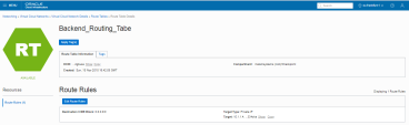
Add these new routing tables to the Private Subnet (the Backend subnet, that you configure after you add the Additional Secondary vNIC) and the Public subnet, respectively. This rule redirects the traffic to the Secondary Private IP address of the Secondary vNIC (traffic goes through the VIP).
-
Add this Route Table to the Public Subnet (Frontend):
-
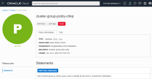
Create a Dynamic Group and include the two Cluster members in this Dynamic Group (in this example, the group name is cp_cluster_group). To create the rules which define the Dynamic Group, use the OCI Rule Builder and create two different rules, one for each Cluster member. If you do not use the OCI Rule Builder, you can manually configure one rule to include the two Cluster members, as appears below.


-
Create the policy and allow the defined Dynamic Group to use resources in the compartment where it belongs.
-
Connect to the two CloudGuard Cluster members with the Private Key matched to the Public Key you used when you created the instance (
ssh –i privateKey admin@<cluster-member-public-ip>). Run these commands in the Clish prompt to set the password:> set user admin password- insert your password <XXXXX>
> save config> exit -
Use a web browser to connect to the Cluster members with the member public IP address. Enter the Blink wizard information to complete the configuration.
https://<member_public_ip>
User name : admin
Password: XXXXX
-
Configure the CloudGuard members and Cluster in the Management SmartConsole
Check Point GUI application used to manage a Check Point environment - configure Security Policies, configure devices, monitor products and events, install updates, and so on..


|
|
Best Practice - Apply the latest GA Jumbo Hotfix Accumulator |
