Installing the CloudGuard Network Security Gateway
To upgrade or install the CloudGuard Network Gateway for NSX-T, open these connections:
-
vSphere Web Client
-
NSX-T manager
-
Console or SSH connections
Make sure you have the latest build of the CPUSE![]() Check Point Upgrade Service Engine for Gaia Operating System. With CPUSE, you can automatically update Check Point products for the Gaia OS, and the Gaia OS itself. Deployment Agent. After you install CloudGuard Network, continue with Step 2.
Check Point Upgrade Service Engine for Gaia Operating System. With CPUSE, you can automatically update Check Point products for the Gaia OS, and the Gaia OS itself. Deployment Agent. After you install CloudGuard Network, continue with Step 2.
Use the steps below as a guide for your system:
| Step | Description |
|---|---|
|
1 |
Install the CloudGuard Network Service Registration Hotfix See Step 1: Installing the CME Bundle on the Management Server. |
|
2 |
Configure the VMware components. |
|
3 |
Provide the OVF URL path. |
|
4 |
Configure the CloudGuard Network Management Server Properties. |
|
5 |
Register the CloudGuard Network Gateway Service. See Step 5: Registering a New CloudGuard Network Gateway Service. |
|
6 |
Deploy and Configure CloudGuard Security Gateway for NSX. See Step 6: Deploying and Configuring CloudGuard Network Security Gateway for NSX. |
Step 1: Installing the CME Bundle on the Management Server
The Cloud Management Extension (CME) is a utility that runs on Check Point Security Management Servers and Multi-Domain Security Management Servers.
CME can be installed on Security Management Servers and Multi-Domain Security Management Servers deployed in cloud platforms or on-premises.
|
|
Important - To keep CME up-to-date with Automatic Updates. To get CME with Automatic Updates, remove any CME manual installation made through CPUSE and refer to sk157492. |
To install the CME utility:
-
Go to sk157492.
-
Download the latest CME package for your Management Server version.
-
Follow the Installation Instructions in the SK article.
Step 2: Configuring the NSX-T Components
Before you start these procedures, install and configure the required VMware component. You can install more than one ESXi.
Preparing the ESXi Cluster for CloudGuard Network Service Deployment
CloudGuard Network services deployed on hosts provide granular control over East-West network traffic.
The services allow guest VM traffic to flow through the security implementation without changing the original topology.
To prepare hosts to participate in NSX-T, you must install NSX-T kernel modules on ESXi hosts.
This allows you to build the NSX-T control-plane and management-plane fabric.
NSX-T kernel modules packaged in VIB files run in the hypervisor kernel and provide services such as distributed routing, distributed firewall and bridging capabilities.
-
Log in to the NSX-T manager Web Client.
-
Select System > Fabric > Nodes > Host Transport Nodes.
-
From the Managed By drop-down list, choose a vCenter.
-
Select the cluster
 Two or more Security Gateways that work together in a redundant configuration - High Availability, or Load Sharing. on which you want to install the NSX VIB, and then click Configure NSX.
The Configure NSX window opens.
-
In Select Deployment Profile, from the drop-down list, choose the relevant profile you created earlier for your ESXi.
-
Click Save.
-
The VIB is automatically installed on the cluster ESXi.
|
|
Notes:
|
NSX NSGroup Objects
With the Grouping feature, you can create custom containers and assign resources, such as virtual machines and network adapters for CloudGuard service protection.
After a group is defined, you can add the group as source or destination to a redirection rule![]() Set of traffic parameters and other conditions in a Rule Base (Security Policy) that cause specified actions to be taken for a communication session..
Set of traffic parameters and other conditions in a Rule Base (Security Policy) that cause specified actions to be taken for a communication session..
|
|
Note - You can include other NSGroups in your new NSGroup. |
-
In the sub-menu, select Inventory > Groups > Groups.
-
Click the + Add icon. The Add New NSGroup window opens.
-
In the General tab, enter a name and description for the new NSGroup.
-
Add objects in the Membership Criteria and Member tabs.
Objects that you select are always included in the NSGroup, even if these objects do not match the dynamic membership specifications.
-
-
From the NSX-T manager Web Client's menu bar, select Advanced Networking & Security.
-
In the sub-menu, select Inventory > Groups > Groups.
-
Click the + Add icon. The Add New NSGroup window opens.
-
In the General tab, enter a name and description for the new NSGroup.
-
Add objects in the Membership Criteria and Member tabs.
Objects that you select are always included in the NSGroup, even if these objects do not match the dynamic membership specifications.
-
Creating a CloudGuard Network Gateway IP Address Pool
-
Log in to the NSX-T manager Web Client.
-
From the NSX-T manager Web Client's menu bar, select Networking in Manager mode.
-
In the sub-menu, select IP Management > IP Address Pools.
-
Click the + Add icon.
The Add New IP Pool window opens.
-
Enter a Name and Description for the IP pool.
-
Enter the IP address range to include in the pool, Subnets mask (CIDR) and its default gateway, and click Add.
-
The IP pool is used when the East-West service is deployed.
Example:

-
Log in to the NSX-T manager Web Client.
-
From the NSX-T manager Web Client's menu bar, select Advanced Networking & Security.
-
In the sub-menu, select Inventory > Groups > IP Pools.
-
Click the + Add icon. The Add New IP Pool window opens.
-
Enter a Name and Description for the IP pool.
-
Enter the IP address range to include in the pool, Subnets mask and its default gateway, and then click Add.
Step 3: Providing the URL OVF Path
Install the OVF files to configure the Security Gateway.
-
<file_name>.ovf -
<file_name>.vmdk -
<file_name>.mf -
<file_name>.cert
-
Download the TGZ package from sk139213.
-
Extract the package and make sure it contains the OVF, VMDK, cert, and MF files.
-
Copy the files to your own location.
-
Add the URL of the CloudGuard Network gateway OVF while you register new service.
Configure this URL to the file with the
*.ovfextension.
|
|
Notes:
|
Step 4: Configuring the Management Server
Configuring the CloudGuard Network Management Server Properties
Log in with SSH to the Management Server in Expert Mode![]() The name of the elevated command line shell that gives full system root permissions in the Check Point Gaia operating system. and run the command:
The name of the elevated command line shell that gives full system root permissions in the Check Point Gaia operating system. and run the command:
|
cme_menu |
Configure the CloudGuard Network Management Server properties.
The controller is the NSX-T manager.
Before you can create new service, it is necessary to add the controller (NSX-T manager) to your environment.
-
Select VMware > NSX-T > Manage NSX-T Controller > Add NSX-T Controller.
-
Enter the Host IP which is the NSX-T manager IP address.
When the thumbprint of the server shows, verify it.
You can get the thumbprint from the NSX-T manager CLI.
Log in as admin, and run:
-
For unclustered NSX-T managers:
get certificate API thumbprint
-
For clustered NSX-T managers:
get certificate cluster thumbprint
-
-
In CME Take 233 and higher: Configure no_proxy value [ True/False ].
If you set the no_proxy variable to True, the CME connects to the NSX-T Manager without using the Proxy configured on the Check Point Management server (if the Proxy exists).
-
Enter the Controller Name.

Notes:
-
The name must be unique for each controller on the Management Server.
-
The name must not exceed 15 characters.
-
-
Enter the Controller User Name.
This is the same username used to log in to the NSX-T manager.
Username supported characters:
-
Upper letters (
A-Z). -
Lowercase letters (
a-z). -
Digits (
0-9). -
Underscore character (
_).
-
-
Enter the Controller User Password, and then confirm.
This is the same password used to log in into the NSX-T manager.
Password requirements:
-
Contains at least 8 characters.
-
Contains both upper letters (
A-Z) and lowercase letters (a-z). -
Contains at least one digit (
0-9). -
Contains at least one special character (
~ ! @ # $ % ^ & * ( ) _ - + =).
-
-
If this is Multi-Domain Server
Dedicated Check Point server that runs Check Point software to host virtual Security Management Servers called Domain Management Servers. Synonym: Multi-Domain Security Management Server. Acronym: MDS. environment, select the domain. -
To confirm the controller is connected select Show NSX controller and confirm your NSX-T controller status is Connected.
If it necessary to change the user name and password for the controller, go to:
VMware> NSX-T > Manage NSX-T Controller > Update NSX-T Controller User.
Step 5: Registering a New CloudGuard Network Gateway Service
Log in with SSH to the Management Server in Expert Mode and run:
|
cme_menu |
After you created the controller, you can now register the new service.
-
Select VMware > NSX-T > Register New Service.
-
Select Attachment Point: East-West or North-South.
-
For East-West service, enter the URL path for the OVF.
-
For North-South service:
-
Select which Tier you want to deploy your service on Tier 0 or Tier 1.
-
Choose Failure Policy.
-
Enter the URL path for the OVF.
-
-
-
Select the NSX-T controller.
-
Enter and then confirm the SIC one-time password for the gateway to be deployed in the NSX-T manager web client.
Note - The SIC
Secure Internal Communication. The Check Point proprietary mechanism with which Check Point computers that run Check Point software authenticate each other over SSL, for secure communication. This authentication is based on the certificates issued by the ICA on a Check Point Management Server. one-time password is a string of 8-12 alphanumeric characters. Special characters are not allowed. -
Enter and then confirm the admin password for the gateway that you want to deploy in the NSX-T manager web client.
The service is now available for deployment on the NSX-T manager web client.
Failure Policy
Failure Policy in East-West Services:
The failure policy for East-West services is determined while redirecting the traffic to the service from the
NSX-T manger web Client. You can change it in the NSX-T web client.
Failure Policy in North-South Services:
The failure policy for North-South services is determined when you deploy the service from the NSX-T manger web Client.
|
|
Important - After installation, you cannot change the failure policy. |
Automatic Provisioning of CloudGuard Network Objects (East-West Only)
In East-West deployment, Automatic Provisioning![]() Check Point Software Blade on a Management Server that manages large-scale deployments of Check Point Security Gateways using configuration profiles. Synonyms: SmartProvisioning, SmartLSM, Large-Scale Management, LSM. handles these actions on CloudGuard Network objects:
Check Point Software Blade on a Management Server that manages large-scale deployments of Check Point Security Gateways using configuration profiles. Synonyms: SmartProvisioning, SmartLSM, Large-Scale Management, LSM. handles these actions on CloudGuard Network objects:
-
Creates CloudGuard Network objects on the CloudGuard Network Management Server when the gateway is ready.
-
Automatically initializes SIC between the CloudGuard Network Gateway and the CloudGuard Network Management Server.
-
Configures Identity Awareness
Check Point Software Blade on a Security Gateway that enforces network access and audits data based on network location, the identity of the user, and the identity of the computer. Acronym: IDA. on the CloudGuard Network Gateway. -
Installs Standard policy on new Security Gateways.
Note - After the policy installation is complete, you can install a different policy on the gateway from the SmartConsole.
To see the current Automatic Provisioning status:
|
|
To enable Automatic Provisioning:
After you create a new controller the service auto-provision starts automatically.
To disable Automatic Provisioning:
|
|
Uninstalling the CloudGuard Network Gateway
|
|
Important - Do not use this procedure to upgrade the CloudGuard Network Service Registration Hotfix. |
Uninstall the CloudGuard Network Gateway service before you uninstall CloudGuard Network from the CloudGuard Network Management Server.
-
Log in to the NSX-T manager web client.
-
Select Security > Network Introspection (E-W) > Rules, and then remove all the rules that apply to the service that you want to delete.
-
Select Service Chain, and then remove the service chain that relates to the service to be deleted.
-
Select Service profile, and then remove the service profile that relates to the service to be deleted.
-
Select System > Service Deployments > Deployment, and then click on the service to be deleted > select Delete.
-
Connect to the management CLI, and then run the CME menu (
cme_menu). -
Select VMware > NSX-T > Manage Registered Service > Remove Service, and then select the service to be deleted.
-
Log in to the NSX-T manager web client.
-
From the Advanced UI (manager) tab, select Security > Partner Services > Service Instances).
-
Select the service that you want to delete.
-
Click undeploy. To confirm, select undeploy.
-
Log in to the NSX-T manager web client.
-
Select Advanced Network & Security > Partner Services > Service Instances.
-
Select the service that you want to delete.
-
Click undeploy. To confirm, select undeploy.
Automatic Provisioning in SmartConsole
-
If you did not enable Automatic Provisioning, delete the gateway manually.
-
If you did enable Automatic Provisioning, wait for the objects to be deleted from SmartConsole.
Management High Availability Failover
Failover from an Active Management Server (Security Management Server![]() Dedicated Check Point server that runs Check Point software to manage the objects and policies in a Check Point environment within a single management Domain. Synonym: Single-Domain Security Management Server. or Multi-Domain Server) to the Standby Management Server is done manually.
Dedicated Check Point server that runs Check Point software to manage the objects and policies in a Check Point environment within a single management Domain. Synonym: Single-Domain Security Management Server. or Multi-Domain Server) to the Standby Management Server is done manually.
You must manually synchronize the Management Servers before and after failover.
To learn more, see the Quantum Security Management Administration Guide for your version > the section "Synchronization Procedures".
|
|
Note - In a Multi-Domain Server environment, synchronize only the Domain Management Server that you changed to Active. It is necessary to do this for every Domain Management Server that was changed to Active. |
-
In SmartConsole, select > Management High Availability.
The High Availability Status window opens.
-
Change the Active Management Server to Standby.
-
Change the Standby Management Server to Active.
-
Select VMware > NSX-T > Manage NSX-T Controller > Update Service Manager IP for HA.
-
Select the controller.
-
Enter the old Security Management Server or Multi-Domain Server IP address.
-
Enter the new Security Management Server or Multi-Domain Server IP address.
This is the IP Address of the Security Management Server or Domain Log Server
Dedicated Check Point server that runs Check Point software to store and process logs. (you can route this IP address from the NSX).The NSX can now send notifications to the new Active Management Server.
-
Repeat Steps 1 and 2 to synchronize the Management Servers.
To learn more about failover, see the Quantum Security Management Administration Guide for your version > the section "Changing a Server to Active or Standby".
|
|
Best Practice - In a Management High Availability environment, store the CloudGuard OVF files on a third-party web server. |

Step 6: Deploying and Configuring CloudGuard Network Security Gateway for NSX
Check Point CloudGuard Network Gateway enforces adaptive security across virtual environments. It applies advanced Threat Prevention to block threats inside the Data Center, and micro-segmentation for access control inside the virtual environment.
Deploying a CloudGuard Network Gateway
After you complete the service registration (see Step 5: Registering a New CloudGuard Network Gateway Service), you can deploy the CloudGuard Network Gateway with the vSphere Web Client.
Before you begin:
-
Make sure you prepared the NSX-T cluster before deploying the service on it. See Preparing the ESXi Cluster for CloudGuard Network Service Deployment.
-
If you use an external data store, make sure you know its details.
-
Review the VMware instructions for "North-South Network Security - Inserting Third-party Service".
-
Log in to the NSX-T manager web client.
-
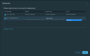
Select System > Service Deployments > Deployment.
-
Select the created service and click Deploy Service.
-
Enter the Service Deployment Name.
-
Select the Compute Manager.
-
Select the Cluster on which to deploy the service.
-
Select Data Store.
-
Select the Network. For eth0, select Network Type static IP pool.
-
Select the Service Segment plus icon. Note - For each Transport Zone there is only one segment.
-
Select Deployment Specification.
-
Select the Deployment Template "CheckPoint_template".
Note - You can change the SIC and the admin password given in the service registration. It is necessary to provide a new SIC in Base64 and the admin password hash.
-
Select a Deployment Type:
-
Host Based - A Gateway is deployed on each ESX in the chosen cluster.
-
Clustered - You need to select a Host (ESX) to deploy the service on, and a clustered deployment count - which is the number of Gateways to be deployed.
-
-
Click Save.
The service is deployed.
|
|
Notes:
|
|
|
Important - If the Installation Status does not succeed, then click Failed to see the reason for the failure. |
-
Log in to the NSX-T manager web client.
Select Security > on the Advanced UI (manager) tab, select Partner Services > Service Instances.
-
Click Deploy.
-
Enter an instance name (the description is optional).
-
Click the Partner Service field > select Check Point CloudGuard for NSX-T service.
-
Select the Deployment Specification esx-01a.corp.local.
-
Select a logical router (only routers that do not have Service Insertion configured are displayed).
-
Click Next.
-
Click the Compute Manager field and select a compute manager.
-
Click the Cluster field and select a cluster.
-
Click the Datastore field and select a datastore
-
Select the Deployment Mode - Standalone
Configuration in which the Security Gateway and the Security Management Server products are installed and configured on the same server. or High Availability. -
Select a Failure Policy - the default action when the Service VM does not function:
-
Allow - The traffic passes without inspection.
-
Block - All traffic is dropped.
-
-
Enter the IP address of the VM (for High Availability enter the network configuration for both VMs).
-
Enter the default Gateway for the VM's IP address.
-
Enter the subnet mask for the VM's IP address.
-
Click Next.
-
Click Finish.
-
Log in to the NSX-T manager web client > Advanced Networking & Security - OR - Security.
-
Click Deploy.
-
Enter an instance name (the description is Optional).
-
Click the Partner Service field > select Check Point CloudGuard for NSX-T service.
-
Select the Deployment Specification esx-01a.corp.local.
-
Select a logical router (only routers that do not have Service Insertion configured are displayed).
-
Click Next.
-
Click the Compute Manager field and select a compute manager.
-
Click the Cluster field and select a cluster.
-
Click the Datastore field and select a datastore.
-
Select the Deployment Mode - Standalone or High Availability.
-
Select a Failure Policy - the default action when the Service VM does not function:
-
Allow - The traffic passes without inspection.
-
Block - All traffic is dropped.
-
-
Enter the IP address of the VM (for High Availability, enter the network configuration for both VMs).
-
Enter the default Gateway for the VM's IP address.
-
Enter the subnet mask for the VM's IP address.
-
Click Next.
-
Click Finish.
Cluster interfaces configuration:
On the deployment of the OVF template, these interfaces are configured:
-
eth0- The Management interface. -
eth1andeth2- The bridge interfaces (ingress and egress respectively). -
eth3- Can operate as the High Availability sync interface.When you use High Availability deployment mode, you must set the IP Addresses for eth3 (Sync Interface) of each node.
In Smart Console:
-
Configure IP address for
eth3(sync interface). -
Set
eth0type: Cluster ,eth3type: primary sync.For example:
-
Disable anti-spoofing on the Cluster members.
-
Reboot the Cluster members.

Configuring NSX to Redirect Traffic to the CloudGuard Network Gateway
This procedure describes basic steps to configure the redirection rules. See Creating Redirection Rules.
For more information, see the VMware documentation for conceptual information, detailed procedures, and explanations of the different objects and options.
After you successfully deployed a service in your environment, for the traffic to be inspected by the deployed service (Check Point Gateway), it is necessary to enable the redirection rules.
|
|
Note - IPv6 is currently not supported for CloudGuard Network Gateway for NSX-T 2.4.x. Make sure to not redirect IPv6 traffic to the CloudGuard Network Gateway. |
Configuring Traffic Redirection in East-West
A Service Profile is an instance of a CloudGuard Network vendor template.
To create a new Service Profile in NSX-T 3.0 and higher:
-
Select Security > select Network Introspection Settings for NSX-T 3.0 > Service Profiles.
-
Select the service to create a profile for, and then click Add Service Profile.
-
Enter the Service Profile Name.
-
Select the vendor template.
The vendors were already created in the service registration.
Their purpose is to expose protection levels in the policies.
To create a new Service Profile in NSX-T 2.5:
-
Select Security > Network Introspection (E-W) > Service Profiles.
-
Select the service to create a profile for, and then click Add Service Profile.
-
Enter the Service Profile Name.
-
Select the vendor template.
The vendors were already created in the service registration.
Their purpose is to expose protection levels in the policies.
A service chain is a logical sequence of service profiles defined by the network administrator.
To create a new Service Chain:
-
Select Security > select Network Introspection (E-W) or Network Introspection Settings > click Service Chains > click Add Chain.
-
Enter a Name for the Service Chain.
-
Enter a Description for the Service Chain.
-
Select a Service Segment.
-
Set the Forward Path with the service profile you created before.
Note - You can have more than one service profile in the forward path.
-
Select a Failure policy.
-
Click Save.
You can now configure the redirection rule that sends the specified traffic to the CloudGuard Network Gateway:
-
Select Security > Network Introspection (E-W) > Rules > Add policy.
A Policy section is similar to the Security Policy section.
Each section belongs to a single Service Chain, but multiple sections can belong to the same Service Chain.
The rules in this section define which traffic is, or is not redirected to the chain.

Important - Some features, as in HTTPS Inspection
Feature on a Security Gateway that inspects traffic encrypted by the Secure Sockets Layer (SSL) protocol for malware or suspicious patterns. Synonym: SSL Inspection. Acronyms: HTTPSI, HTTPSi., require you to disable the stateful inspection of the packets by the VMware firewall (DFW):-
Click Add Policy.
-
From the toolbar, click the settings icon.
-
Change Stateful to No.
-
-
Select to which Service Chain the policy is redirected to, and then click Add Rule:
-
Choose a name for the rule.
-
Choose a Traffic Source. It can be NSgroups, VM, IP, and more.
-
-
Select a Traffic Destination. It can be NSgroups, VM, IP, and more.
-
Select on which policy it is applied to (the DFW or any groups already created).
-
Make sure the check box is green.
-
Click Publish to apply the changes.
Configuring Traffic Redirection in North-South
|
|
Note - You must allow BFD packets to pass through the Security Gateway for correct functionality of North/South traffic redirection. Add a rule allowing BFD packets to the Security Management policy. |
-
From the Advanced UI (manager) tab, select Security) > Partner Services > click the service that needs the traffic redirection configured.
-
Go to the Traffic Redirection tab.
-
Next, add a section.
A section is collection of one or more firewalls.
To add a section, select an existing section and then click Add Section.
-
Click Add Section Above or Add Section Below.
-
A new section is created:
-
The traffic type to be redirected is set to L3 Redirect.
-
The service type is Stateless.
-
The Applied To field is associated to a Tier-0 logical router that is configured on the host.
After you define rules, the Rules field is populated automatically.
-
-
-
To keep configuration details on the section, click Publish.
-
To add a rule in that section, select the section and then click Add Rule.
-
In the rule row, enter these details:
-
Enter a name for the rule.
-
Enter the source and destination of L3 traffic.
The partner service VM introspects traffic that flows in from the source before redirecting it to the destination VM.
-
In the Applied To field, select the uplink of Tier-0 router.
-
In the Action field:
-
Select Redirect if traffic needs to be introspected by the service VMs.
-
Select Don't Redirect if traffic does not need to be introspected for North-South introspection.
-
-
-
Each rule can be individually enabled.
After you enable a rule, it is applied to the traffic that matches the rule.
-
To configure the traffic direction and to enable logging, click Advanced Settings.
-
At the end of a section that contains rules:
-
Click Publish to keep the rules in the section.
-
Click Revert to cancel the operation.
-
-
Go to Security > Network Introspection (N-S).
A policy section is similar to a firewall section in that you define rules that determine how traffics flows.
-
Set Redirection To, to the service instance that is registered with NSX-T to perform network introspection of traffic that flows between source and destination entities.
-
To add a policy, click Publish.
-
Click the vertical ellipsis on a section and click Add Rule.
-
To add a group by definition of membership criteria, static members, IP/MAC addresses, or active directory groups, edit the Source field.
Membership criteria can be defined from one of these types: Virtual Machine, Logical Switch, Logical Port, and IP Set.
You can select static members from one of these categories: Group, Segment, Segment Port, Virtual Network
Environment of logically connected Virtual Machines. Interface, or Virtual Machine. -
Click Save.
-
To add a destination group, edit the Destination field.
-
In the Applied To field, you can do one of these:
-
Select DFW to apply the rule to all virtual NICs attached to the logical switch.
-
Select VM groups to apply the rule on virtual NICs of member VMs of the group.
Members can be selected from a static list or based on dynamic criteria.
The supported NSX-T Data Center objects are: Virtual Machine, Logical Switch, Logical Port, IP Set, and more.
-
-
In the Action field:
-
Select Redirect to redirect traffic along the service instance.
-
Select Do Not Redirect to not apply network introspection on the traffic.
-
-
Click Publish.
-
To revert to a published rule, select the rule and then click Revert.
-
To add a policy, click + Add Policy.
-
To clone a policy or a rule, select the policy or rule and then click Clone.
-
To enable a rule, enable the Enable/Disable icon or select the rule and then from the menu click Enable > Enable Rule.
-
After a rule is enabled or disabled, click Publish to enforce the rule.
-
From Advanced Networking & Security.
-
Go to the Traffic Redirection tab.
-
Next, add a section.
A section is collection of one or more firewalls.
To add a section, select an existing section and click Add Section.
-
Click Add Section Above or Add Section Below.
-
A new section is created.
-
The traffic type to be redirected is set to L3 Redirect.
-
The service type is Stateless.
-
The Applied To field is associated to a Tier-0 logical router that is configured on the host.
After you define rules, the Rules field is populated automatically.
-
-
-
To keep configuration details on the section, click Publish.
-
To add a rule in that section, select the section and then click Add Rule.
-
In the rule row, enter these details:
-
Enter a name for the rule.
-
Enter the source and destination of L3 traffic.
The partner service VM introspects traffic that flows in from the source before redirecting it to the destination VM.
-
In the Applied To field, select the uplink of Tier-0 router.
-
In the Action field:
-
Select Redirect if traffic needs to be introspected by the service VMs.
-
Select Don't Redirect if traffic does not need to be introspected for North-South introspection.
-
-
-
Each rule can be individually enabled.
After you enable a rule, it is applied to the traffic that matches the rule.
-
To configure the traffic direction and to enable logging, click Advanced Settings.
-
At the end of a section that contains rules:
-
Click Publish to keep the rules in the section.
-
Click Revert to cancel the operation.
-
-
Go to Security > North South Firewall > Network Introspection (N-S).
A policy section is similar to a firewall section in that you define rules that determine how traffics flows.
-
Set Redirection To to the service instance that is registered with NSX-T to perform network introspection of traffic that flows between source and destination entities.
-
To add a policy, click Publish.
-
Click the vertical ellipsis on a section and click Add Rule.
-
To add a group by definition of membership criteria, static members, IP/MAC addresses, or active directory groups, edit the Source field.
Membership criteria can be defined from one of these types: Virtual Machine, Logical Switch, Logical Port, and IP Set.
You can select static members from one of these categories: Group, Segment, Segment Port, Virtual Network Interface, or Virtual Machine.
-
Click Save.
-
To add a destination group, edit the Destination field.
-
In the Applied To field:
-
Select DFW to apply the rule to all virtual NICs attached to the logical switch.
-
Select VM groups to apply the rule on virtual NICs of member VMs of the group.
Members can be selected from a static list or based on dynamic criteria.
The supported NSX-T Data Center objects are: Virtual Machine, Logical Switch, Logical Port, IP Set, and more.
-
-
In the Action field:
-
Select Redirect to redirect traffic along the service instance.
-
Select Do Not Redirect to not apply network introspection on the traffic.
-
-
Click Publish.
-
To revert to a published rule, select the rule and then click Revert.
-
To add a policy, click + Add Policy.
-
To clone a policy or a rule, select the policy or rule and then click Clone.
-
To enable a rule, enable the Enable/Disable icon or select the rule and then from the menu click Enable > Enable Rule.
-
After a rule is enabled or disabled, click Publish to enforce the rule.
Manually Creating CloudGuard Network Objects in SmartConsole
This procedure is not necessary if you use East-West and already enabled Automatic Provisioning of CloudGuard Network objects.
-
Click the Objects menu > Objects Explorer > More Object Types > Network Objects > Gateways and Servers > Gateway.
-
The Security Gateway object opens on the General Properties page.
-
In the Name field, enter a name for the Security Gateway object.
-
In the IPv4 Address field, enter the IPv4 address.
-
Click Communication.
-
In the Trusted Communication window:
-
Enter the SIC one-time password you configured when you deployed the VM.
-
Click Initialize.
-
Wait for the Trust state to change to Trust established.
-
Click OK.
You are back on the General Properties page.
-
-
In the Platform section, in the Version field, select the correct version.
-
On the Network Security tab, select the required Software Blades.
-
From the left tree, click the Network Management page:
-
Double-click the interface eth0.
-
For HA Cluster, configure Interface Type as Cluster.
-
In the Topology section, click Modify.
-
In the Leads To section, select Override > This Network (Internal) > Network defined by the interface IP and Net Mask.
-
In the Anti-Spoofing section, clear Perform Anti-Spoofing based on interface topology.
-
Click OK to close the Topology Settings window.
-
Click OK to close the Interface window.
-
-
For HA Cluster, configure interface type:
-
Double-click the interface eth3.
-
Configure Interface Type as Primary + Sync.
-
-
Click OK.
-
For HA Cluster, reboot all Cluster members.
|
|
Note - Before you add a CloudGuard Network Gateway instance to the CloudGuard Network cluster, make sure that you coordinate the Date, Time and Time Zone settings between the Security Management Server and the CloudGuard Network Gateway. |
Multi-Tenancy Support
CloudGuard Network supports multi-tenant protection on ESXi.
This means it can protect multiple customers or organizations as well as departments or business units that share the same ESXi cluster.
-
Dedicated cluster for each tenant. Each tenant's traffic is handled by a single service deployed on the cluster.
This enforces the Security Policy
Collection of rules that control network traffic and enforce organization guidelines for data protection and access to resources with packet inspection. that applies to the security groups for the specific tenant. -
Tenants share the same cluster.
This solution requires a service registration for each tenant.
Manage each tenant through a different service.
To control the tenant traffic redirection, separate security groups have to be created for each tenant.
-
Register a new service with a unique name that identifies the tenant.
-
Deploy the service on the required cluster.
A service instance is added to each host in the cluster.
-
Create a new security group for the tenant. Include all objects that require protection.
-
Redirect each tenant's traffic through the designated service.
Configuring Identity Awareness in SmartConsole
Configure CloudGuard Network to use Identity Awareness to see Security Group details in the CloudGuard Network logs.
-
From the left navigation panel, click Gateways & Servers.
-
If there is no Host object with the IP address
127.0.0.1, then create one. -
Double-click the CloudGuard Gateway object.
-
On the Network Security tab, enable the Identity Awareness Software Blade
Specific security solution (module): (1) On a Security Gateway, each Software Blade inspects specific characteristics of the traffic (2) On a Management Server, each Software Blade enables different management capabilities.. -
In the Identity Awareness Configuration wizard:
-
Select only Terminal Servers > click Next.
-
Select I do not wish to configure an Active Directory at this time > click Next.
-
Click Finish.
-
-
From the left tree, click the Identity Awareness page.
-
Select Identity Web API > click Settings.
-
In the Identity Web API Settings window:
-
In the Client Access Permissions section, click Edit.
-
In the Accessibility window, select Through all interfaces > click OK.
-
In the Authorized Clients section, click the [+] button > select the Host object with the IP address
127.0.0.1. -
Optional: In the Authentication Settings section, click Settings > configure the applicable settings > click OK.
-
Click OK.
-
-
Click OK.
-
Install the Access Control policy.
Configuring the Anti-Virus Policy in SmartConsole
To use the Anti-Virus![]() Check Point Software Blade on a Security Gateway that uses real-time virus signatures and anomaly-based protections from ThreatCloud to detect and block malware at the Security Gateway before users are affected. Acronym: AV. Software Blade in CloudGuard Network for NSX, create a new Threat Prevention profile (this is the profile that you used in the Threat Prevention Policy).
Check Point Software Blade on a Security Gateway that uses real-time virus signatures and anomaly-based protections from ThreatCloud to detect and block malware at the Security Gateway before users are affected. Acronym: AV. Software Blade in CloudGuard Network for NSX, create a new Threat Prevention profile (this is the profile that you used in the Threat Prevention Policy).
-
From the left navigation panel, click Security Policies.
-
In the top section Threat Prevention, click Custom Threat Prevention.
-
In the bottom section Custom Policy Tools, click Profiles.
-
Select the applicable Threat Prevention profile with the enabled Anti-Virus Software Blade > click Edit.
-
In the left panel, click the Anti-Virus page.
-
In the Protected Scope section, select Inspect incoming and outgoing files.
-
Click OK.
-
Install the Threat Prevention policy.
Configuring HTTPS Inspection
To use the HTTPS Inspection Blade in CloudGuard Network for NSX, see the Threat Prevention Administration Guide for your version > Chapter "HTTPS Inspection".
|
|
Notes:
|
Advanced Configuration
For the advanced configuration, use the autoprov_cfg utility.
See the "Using the autoprov_cfg Command Line Configuration utility" section in the Cloud Management Extension Administration Guide.