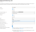
Network
Follow this network diagram to configure your system. Make sure to replace the IP addresses in the sample environment with the IP addresses in your environment.
Network Diagram
|
1 |
Example 1 |
Frontend Web:443 |
Backend port 8081 |
|
2 |
Example 2 |
Frontend App:80 |
Backend port 8083 |
|
3 |
Destination |
Nexthop |
|
|
10.0.0.0/16 |
None (Drop) |
|
|
10.0.1.0/24 |
Virtual Network |
|
4 |
Destination |
Nexthop |
|
|
0.0.0.0/0 |
None (Drop) |
Routing Table for Web and App - User Defined Routes (UDR)
Web and App routing tables have the same Virtual Network address, but different subnet addresses.
|
5 |
Frontend |
Nexthop |
|
|
10.0.0.0/16 - Virtual Network address |
10.0.2.4 -IP of the Internal Load Balancer |
|
|
0.0.0.0/0 |
10.0.2.4 -IP of the Internal Load Balancer |
|
|
10.0.3.0/24 (Web) - Subnet address |
Virtual Network |
|
6 |
Frontend |
Nexthop |
|
|
10.0.0.0/16 -Virtual Network address |
10.0.2.4 -IP of the Internal Load Balancer |
|
|
0.0.0.0/0 |
10.0.2.4 -IP of the Internal Load Balancer |
|
|
10.0.4.0/24 (App) - Subnet address |
Virtual Network |
Diagram Components
The diagram shows:
-
Virtual Network in Azure that is divided into four subnets
-
Frontend
-
Backend
-
Web
-
App
-
-
On-premises network with these components
Check Point High Availability contains two Cluster![]() Two or more Security Gateways that work together in a redundant configuration - High Availability, or Load Sharing. Members, Member 1 and Member 2. Each Cluster Member
Two or more Security Gateways that work together in a redundant configuration - High Availability, or Load Sharing. Members, Member 1 and Member 2. Each Cluster Member![]() Security Gateway that is part of a cluster. has two interfaces.
Security Gateway that is part of a cluster. has two interfaces.
When the Cluster Members are in the same Availability Set, it guarantees that the two Cluster Members are in separate fault domains. For more information, see Manage the availability of Windows virtual machines in Azure.
In the diagram:
-
The cluster protects two web applications.
-
There is Site-to-Site VPN connectivity between the Cluster Members and on-premises Security Gateways.
Each web application has:
-
Public IP address
-
Web server
-
Application server
You must manually configure these components:
-
Backend hosts
-
Subnets
-
Routing tables for Web and App servers
|
Name |
Attached to |
Use |
|---|---|---|
|
Cluster public address |
The external interface of the Active Cluster Member. |
VPN |
|
Cluster private address |
The external interface of the Active Cluster Member. |
VPN |
|
Member 1 public address |
The external interface of Member 1. |
Do not disable or delete this resource. |
|
Member 2 public address |
The external interface of Member 2. |
Do not disable or delete this resource. |
|
Web |
Azure Load Balancer |
Public service Web |
|
App |
Azure Load Balancer |
Public service App |
You cannot use these ports:
-
80
-
443
-
444
-
8082
-
8880
-
8117
|
Frontend IP address |
Frontend TCP ports |
Destination IP address |
Destination port |
|---|---|---|---|
|
Web |
HTTPS |
Active Cluster Member |
8081 |
|
App |
HTTP |
Active Cluster Member |
8083 |
Failover
-
The Cluster Member that fails, immediately stops responding to the Load Balancer health probes.
-
The Cluster Member that gets promoted to Active, starts responding to the Load Balancer health probes.
-
The Azure External Load Balancer and Internal Load Balancer detect the new health status of each Cluster Member and forward traffic to the healthy Cluster Member. For more information, see Azure Load Balancer health probes.
This usually happens in less than 15 seconds based on the health probe Load Balancer configuration. This affects inbound and East-West traffic inspection.
-
The Cluster Member that gets promoted to Active uses the Azure API to associate itself with the cluster's private and public IP addresses.
This usually happens in less than 2 minutes. This affects VPN tunnel failover.
|
Use Case |
Expected Failover Time |
Comments |
|---|---|---|
|
Site-to-Site VPN |
Less than 2 minutes |
Depends on the Azure API. |
|
Inbound inspection through the External Load Balancer |
Less than 15 seconds |
Depends on the Load Balancer health probe. |
|
Outbound inspection through the Internal Load Balancer |
Less than 2 minutes |
Depends on the Load Balancer health probe and Azure API. |
|
East-West inspection through the Internal Load Balancer |
Less than 15 seconds |
Depends on the Load Balancer health probe. |
Traffic Flows
If the Management Server![]() Check Point Single-Domain Security Management Server or a Multi-Domain Security Management Server. is in the Virtual Network, make sure to have specific routes to allow traffic between the Management Server Virtual Machine and the Cluster Members.
Check Point Single-Domain Security Management Server or a Multi-Domain Security Management Server. is in the Virtual Network, make sure to have specific routes to allow traffic between the Management Server Virtual Machine and the Cluster Members.
|
|
Note - It is not possible to deploy other Virtual Machines in the Check Point solution subnets. |
Inbound Traffic
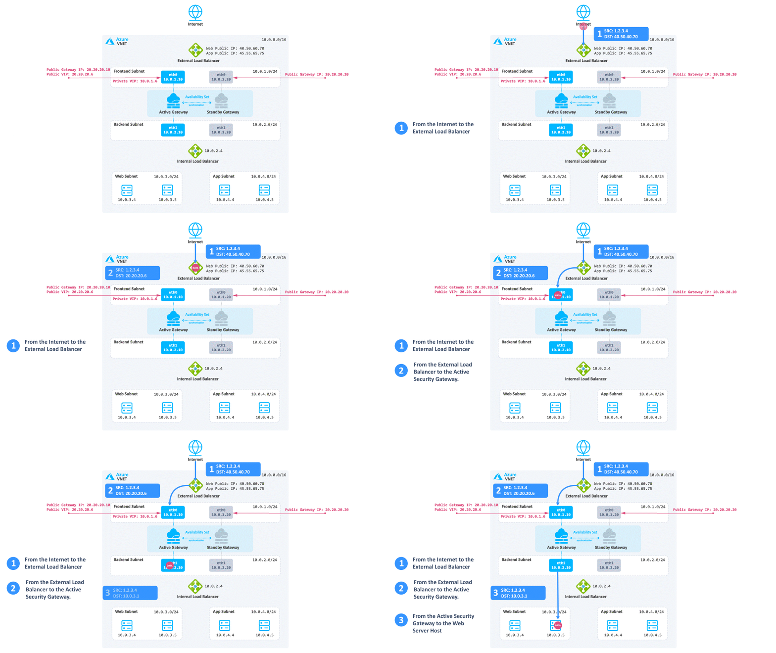
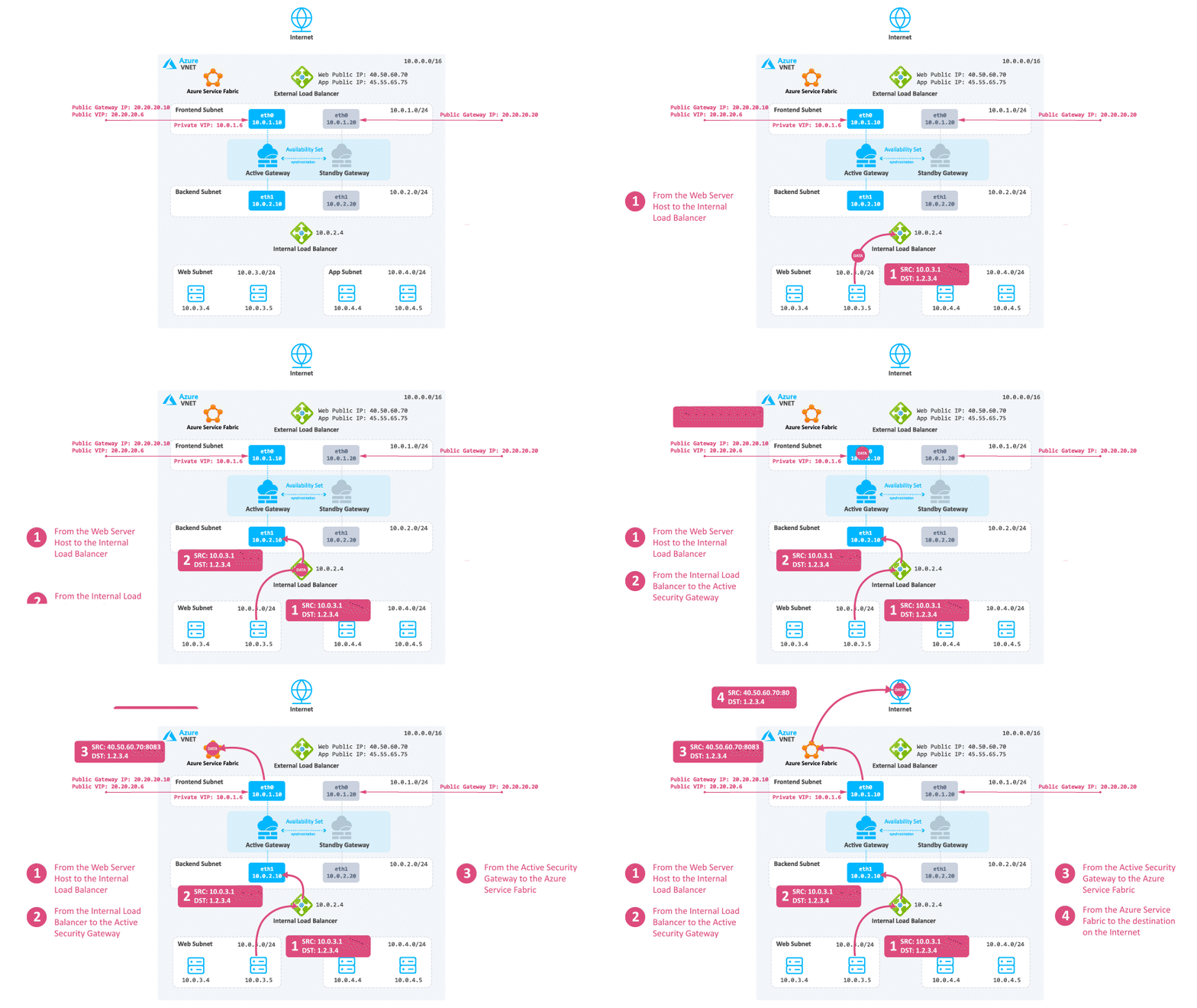
Consider a case when client traffic from the Internet wants to get to a resource behind the Azure High Availability Cluster:
-
The traffic reaches the Web Public IP on port 80 that is associated on the External Load Balancer.
-
The External Load Balancer translates the port from 80 to 8083 and forwards the traffic to the active Security Gateway.
-
The active Security Gateway translates the traffic:
-
Source - Original
-
Destination - Internal Load Balancer IP address or Web server IP address
-
Destination port - 80
-
|
|
Note - Traffic leaving |
-
The reply travels from the Web server to the Internal Load Balancer.
-
The Internal Load Balancer forwards the traffic to the active Security Gateway.
-
The active Security Gateway inspects the traffic, performs NAT on the reply, and forwards it to the destination.
|
|
Notes:
|
-
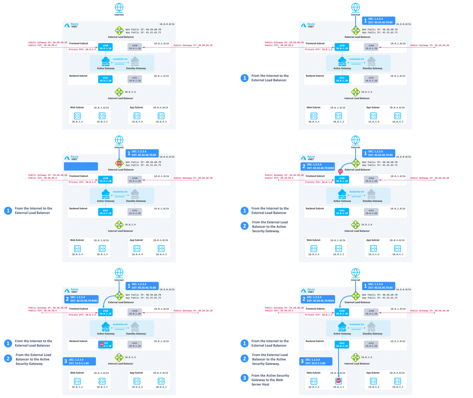
The traffic reaches the Web Public IP on port 80 that is associated on the External Load Balancer.
-
The External Load Balancer translates the port from 80 to 8083 and forwards the traffic to the active Security Gateway.
-
The active Security Gateway translates the traffic:
-
Source - Original
-
Destination - When you enable Floating IP address, Azure changes the IP address mapping to the Frontend IP address of the Load Balancer frontend instead of backend instance's IP address.
-
Destination port - 80
-
|
|
Note - You can enable Floating IP address in the relevant load balancing rules. |
-
The reply travels from the Web server to the Internal Load Balancer.
-
The Internal Load Balancer forwards the traffic to the active Security Gateway.
-
The active Security Gateway inspects the traffic and performs NAT on the reply.
-
The Azure fabric reverses the NATed port and forwards the reply to the destination.
|
|
Note - |
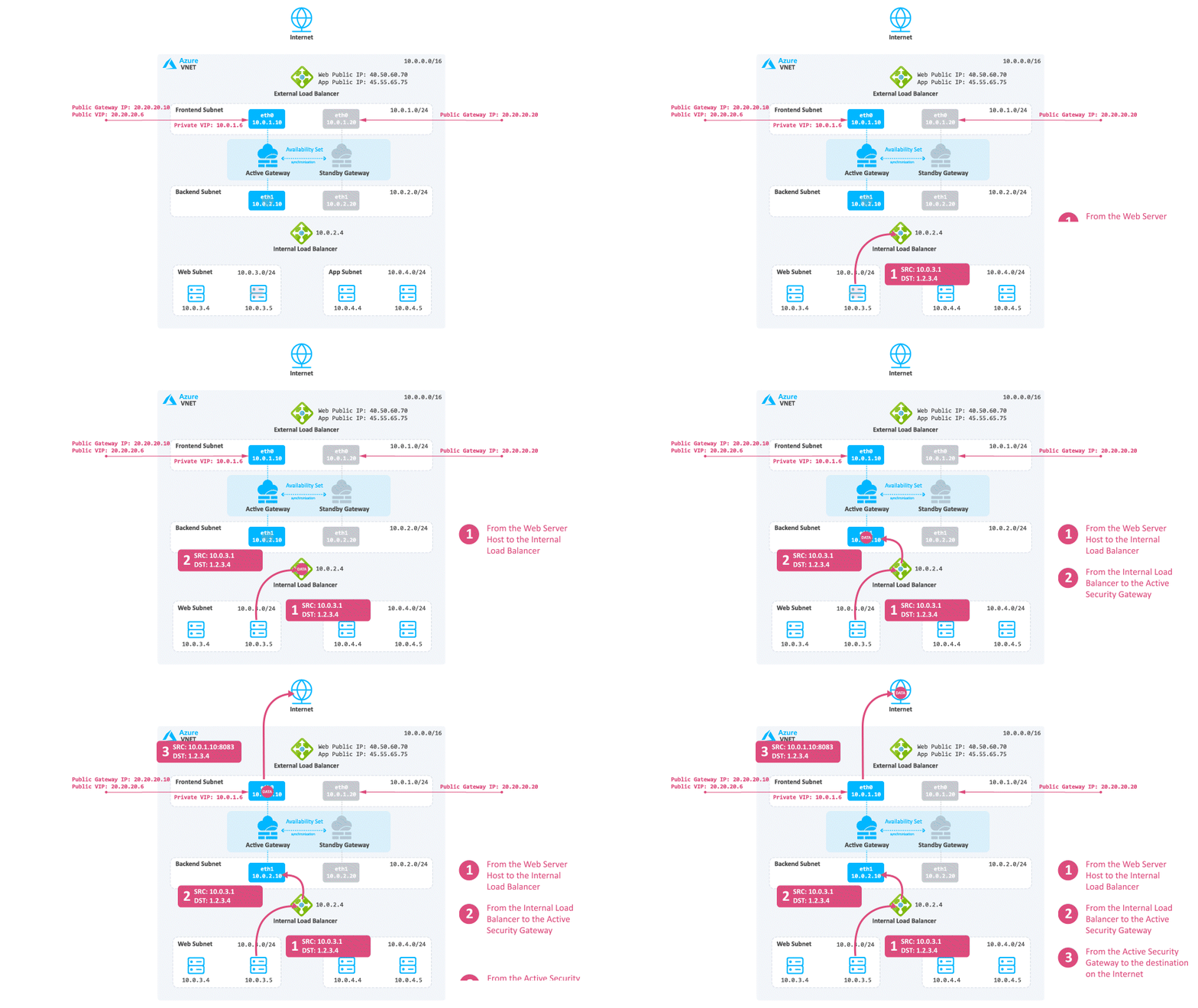
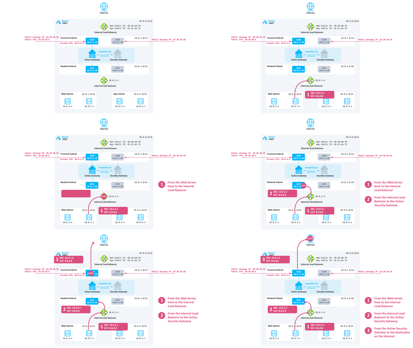
Consider a case when North -South traffic is not needed:
-
Traffic travels from the Web server to the Internal Load Balancer based on the UDR.
-
The Internal Load Balancer forwards the traffic to the active Security Gateway.
-
The active Security Gateway inspects the traffic, performs Hide NAT on the packet to the Private Cluster IP address or its frontend IP address (depending on your configuration) and sends it to the destination.
 Note - Azure will NAT the IP address from the Private IP address to Public IP address.
-
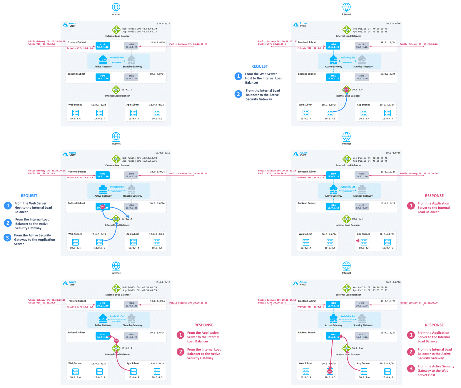
Traffic travels from the internal Web server to the Internal Load Balancer of the Check Point solution.
-
The Internal Load Balancer forwards the traffic to the active Security Gateway.
-
The active Security Gateway inspects the traffic and forwards it to the internal application server.
-
The application server sends a reply to the Internal Load Balancer based on the UDR.
-
The Internal Load Balancer sends the request to the active Security Gateway.
-
The active Security Gateway inspects the traffic and forwards it to the internal Web server.
The Internal Load Balancer deploys by default as part of the solution template and is automatically configured. It is configured to listen and forward any TCP or UDP traffic High Availability ports. It gets an automatically assigned name: backend-lb.
Azure sends probes from the source IP address 168.63.129.16 to TCP port 8117 to monitor the health of the Cluster Members.
Intra-Subnet Traffic
Traffic travels freely in the subnet without inspection.


