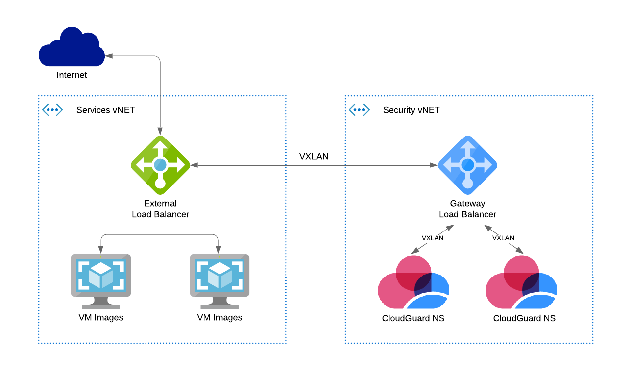
Traffic Flows in Cloud Firewall for Azure VMSS GWLB
Traffic flow explanation
Inbound:
-
The External Load Balancer redirects all packets to the Gateway Load Balancer.
The VXLAN tunnel preserves the original source and destination addresses.
-
The Gateway Load Balancer send a packet to the next healthy Cloud Firewall Gateway
 Check Point Virtual Security Gateway that protects dynamic virtual environments with policy enforcement. Cloud Firewall Gateway inspects traffic between Virtual Machines to enforce security, without changing the Virtual Network topology..
 -
The Cloud Firewall Gateway decides if to forward or drop the packet.
-
The External Gateway Load Balancer sends the inspected packet to the next VM in the Backend Pool.
-
The External Load Balancer redirects reply packets to the Gateway Load Balancer.
-
Symmetrical hashing returns the packet to the original Cloud Firewall Gateway to keep state.
-
The External Load Balancer sends the return packet to the original source address.
When inbound traffic arrives, the Cloud Firewall Gateway receives it follows:
-
VXLAN tunneled traffic with:
-
Source: The Gateway Load Balancer frontend IP.
-
Service: UDP services with the VXLAN tunnel interfaces port numbers (internal & external).
-
Destination: The VMSS instance.
-
-
Encapsulated traffic with:
-
Source: Original source.
-
Service: Original service.
-
Destination: Original (the Frontend IP address of the External Load Balancer).
-
|
|
Note - The traffic flow is the same for the Load Balancing rule |

Outbound:

-
The External Load Balancer receives traffic from a Backend Pool VM.
The External Load Balancer redirects all packets to the Gateway Load Balancer.
The VXLAN tunnel preserves the original source and destination addresses.
-
The Gateway Load Balancer sends the packet to the next healthy Cloud Firewall Gateway.
-
the Cloud Firewall Gateway decides if to forward or drop the packet.
-
The External Load Balancer sends the request packet to the original destination address.
-
The External Load Balancer redirects the reply packet to the Gateway Load Balancer.
-
Symmetrical hashing returns the packet to the original Cloud Firewall Gateway to keep state.
-
The External Gateway Load Balancer sends the inspected reply packet to the original source address, a Backend Pool VM.
When outbound traffic arrives, the Cloud Firewall Gateway receives it follows:
-
VXLAN tunneled traffic with:
-
Source: The Gateway Load Balancer frontend IP address.
-
Service: UDP services with the VXLAN tunnel interfaces port numbers (internal & external).
-
Destination: The VMSS instance.
-
-
Encapsulated traffic with:
-
Source: Original source (The Frontend IP address of the External Load Balancer).
-
Service: Original service.
-
Destination: Original destination.
-
Gateway Load Balancer Frontend Routing Table - User Defined Routes (UDR):
| Name | Destination | Nexthop |
|---|---|---|
|
Local-Subnet |
Gateway Load Balancer Frontend subnet |
Virtual network |
|
To-VNet |
Gateway Load Balancer VNet: |
None (drop) |