Installing the Quantum Smart-1 600-M Telescoping Rails
You can install the Smart-1 600-M Security Management Appliance in a rack with the Telescopic Rails hardware.
Before You Begin

|
Warning - Before you begin, follow the safety instructions included in the Safety, Environmental, and Regulatory Information document shipped with the appliance. |

|
Best Practice - We recommend that at least two people install the Security Management Appliance in a rack to prevent injury, or damage to it. |
General Requirements for Racks
Check Point 1U Security Management Appliances are designed for a standard 19-inch (48.26 cm) rack (see specification EIA-310-D).
The telescopic rails can be used with racks that have round holes, square holes, or threaded holes.
The telescopic rails are designed for racks with these specifications:
Front and rear rack doors must have equally distributed holes on at least 65% of the surface area to give sufficient airflow.
Make sure that the racks have sufficient clearance to service the Check Point Security Management Appliances that are mounted on telescopic rails.
|
Rack Side |
Clearance Requirement |
|---|---|
| Front | 36 in (91.4 cm) plus additional clearance, if necessary, for the mechanical lift used to move the Security Management Appliance and rails equipment. |
| Rear |
16 in (40.6 cm) from the rear of the rack or Security Management Appliance without the rear cabinet door. 22 in (55.9 cm) from the rear of the rack or Security Management Appliance with the rear cabinet door. |
Smart-1 600-M Security Management Appliance Physical Specifications
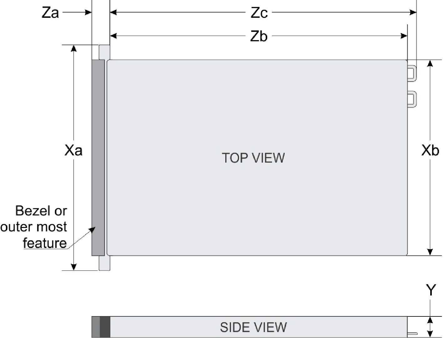
|
Xa |
Xb |
Y |
Za |
Zb |
Zc |
|---|---|---|---|---|---|
|
482.0 mm (19.98 in) |
434.0 mm (17.08 in) |
42.8 mm (1.68 in) |
With bezel: 35.64 mm (1.4 in) Without bezel: 22.0 mm (0.87 in) |
534.5 mm (21.04 in) |
573.6 mm (22.58 in) |
Identifying the Rail Kit Contents
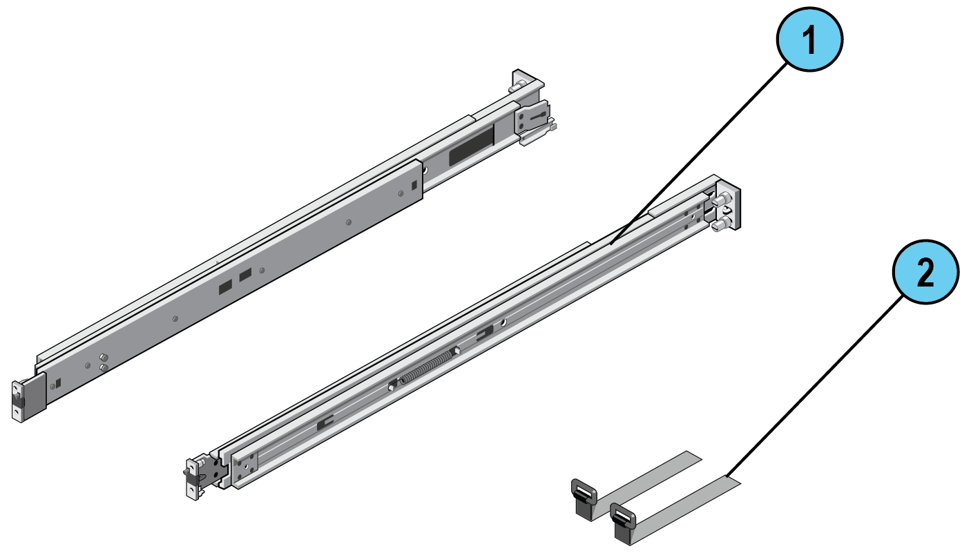
Locate the components for installing the rail kit assembly:
-
Two A12 sliding rail assemblies in a carton labeled:
1U, A12 rack Telescoping Rails (1)
-
Two hook-and-loop straps (2)
Installing and Removing Tool-less Rails
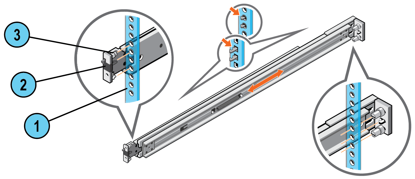
The rails are suitable for both square or round hole racks.
|
|
Important - When installing rails in a square-hole rack, ensure that the pins completely slide through the square holes and the rail end pieces are fully seated on the rack flange. |
To install the rails:
-
Hold the rails so that rail end pieces labeled FRONT are facing the front side of the vertical rack flanges.
-
Align each end piece in the bottom and top holes of the desired U spaces.
-
Engage the back rail end piece until it is seated on the vertical rack flange and the latch clicks into place.
-
Repeat these steps to position and seat the front end piece on the vertical rack flange.
To remove the rails:
Pull the release latches to release the end pieces and then disengage each rail from the rack.
|
Item |
Description |
|---|---|
|
1 |
Rack flange |
|
2 |
Release latch (2) |
|
3 |
Rail end piece (2) |
Installing and Removing Tooled Rails
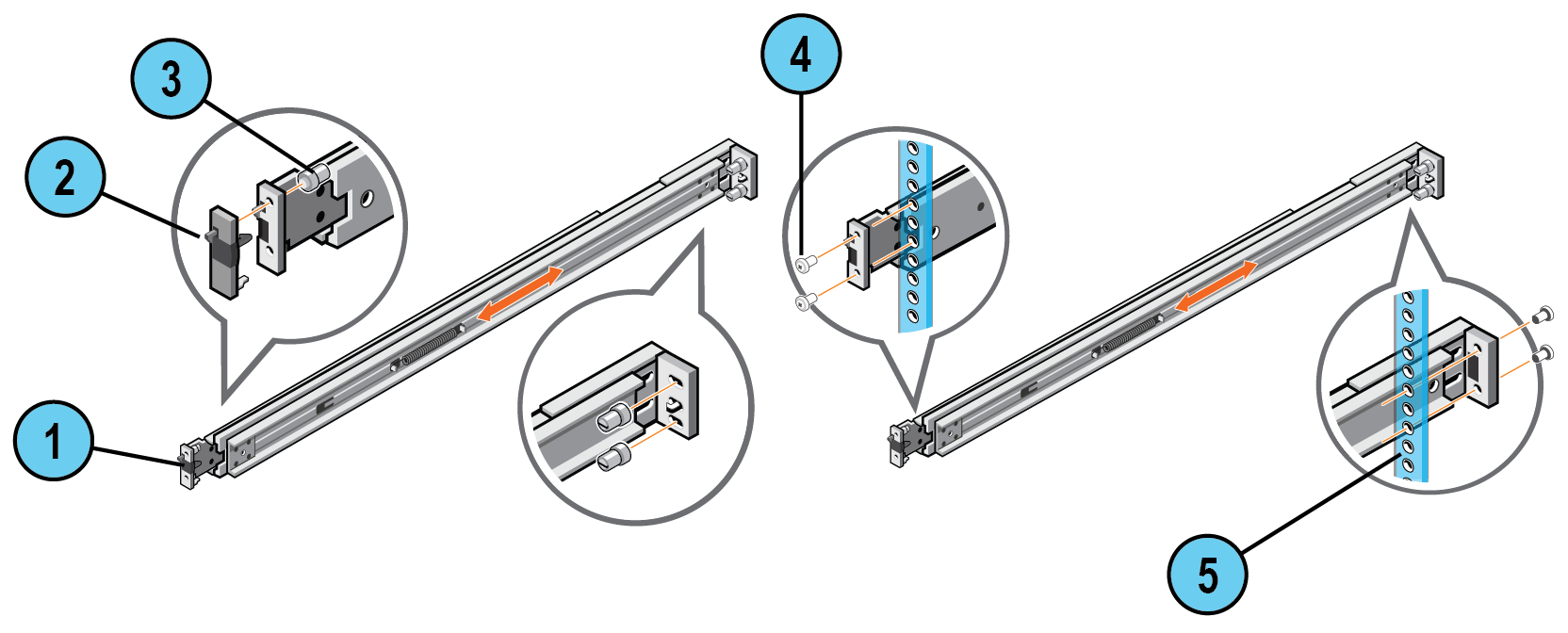
This procedure applies to threaded hole racks. Make sure you have two pairs of screws suitable for your rack.
To install tooled rails:
-
Remove the pins from the front and rear mounting brackets using a flat-tipped screwdriver.
-
Pull and rotate the rail latch subassemblies to remove them from the mounting brackets.
-
Hold the rails so that the rail end pieces labeled FRONT are facing the front of the rack flanges.
-
Secure the mounting rails to the rack flanges by using two pairs of screws.
To remove tooled rails:
Remove the screws on the mounting brackets and disengage each rail from the rack.
|
Item |
Description |
|---|---|
|
1 |
Sliding rail |
|
2 |
Rail latch subassembly (2) |
|
3 |
Pin (3) |
|
4 |
Screw (4) |
|
5 |
Rack flange |
Installing and Removing the Appliance in the Rack
|
|
Important - We recommend that at least two people install/remove the Security Management Appliance in/from a rack to prevent injury, or damage to it. |
To install the Security Management Appliance in the rack:
-
Pull the inner slide rails out of the rack until they lock into place.
-
Align the rear rail standoff on each side of the Security Management Appliance with the rear J-slots on the slide rail assemblies, and lower the appliance until the remaining standoffs engage in the J-slots (see the next figure).
-
Push the Security Management Appliance inward until the server-lock latches on the rails click into place.
-
Press the slide-release lock latches on both rails and slide the Security Management Appliance into the rack until the slam latches engage with the rails.
|
|
Note - To secure the appliance for shipment in the rack or for other unstable environments, locate the screw under each slam latch and tighten each screw by using Phillips #2 screwdriver. |
To remove the Security Management Appliance from the rack:
-
Rotate the slam latches upward, on each side of the appliance, to release the system.
-
Hold the sides of the appliance and pull it forward until the inner slide rails are fully extended.
-
Rotate and hold the server-lock latch while pulling the appliance firmly to slide the standoffs to the front of the J-slots.
-
Lift the system out of the rack.
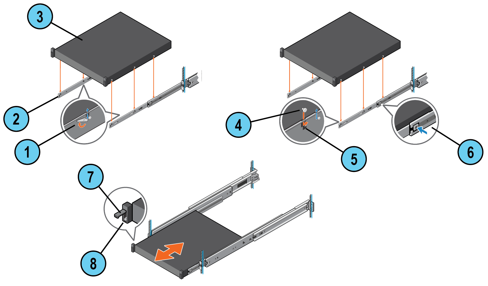
|
Item |
Description |
|---|---|
|
1 |
Server-lock latch (2) |
|
2 |
Inner slide rail (2) |
|
3 |
Security Management Appliance |
|
4 |
Standoff on the appliance |
|
5 |
J-slot on the rail |
|
6 |
Slide-release lock latch (2) |
|
7 |
Slam latch (2) |
|
8 |
Screw (2) |
Installing and Removing the Inner CMA Brackets
To install the inner CMA bracket:
-
Match the SIDE A or SIDE B marking on the brackets to the SIDE A or SIDE B marking on the inner slide rails.
-
Align the holes on the bracket with the standoffs on the slide rail and push the bracket down until it locks into place.
To remove the inner CMA bracket:
-
Press the release tab and slide the support bracket up.
-
Disengage the brackets
|
|
Note - The inner CMA brackets are pre-installed on the rails. Ensure that you remove the inner CMA brackets before removing the power supplies. |
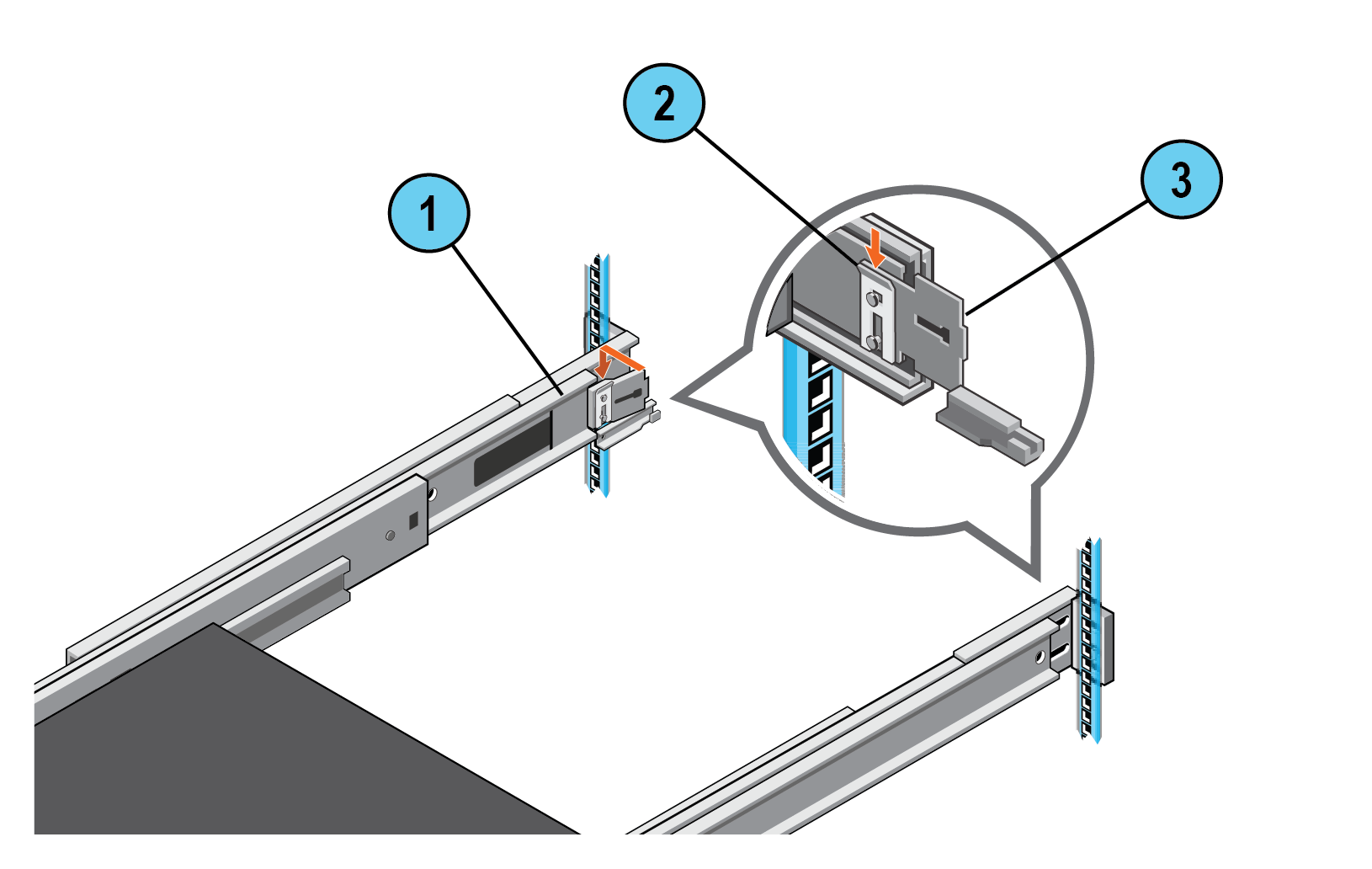
|
Item |
Description |
|---|---|
|
1 |
Sliding rail (2) |
|
2 |
Release tab (2) |
|
3 |
Inner CMA bracket (2) |
Routing the Cables
|
|
Caution - The hook-and-loop straps must be threaded through the tooled slots of the inner CMA brackets and the cable service loops should be created close to the inner CMA brackets. |
|
|
Note -Use the two hook-and-loop straps provided in the rail kit to help route the cables to the rear of your system. |
To route the cables:
-
Bundle the cables to pull them clear of the system connectors, to the left and right sides.
-
Thread the hook-and-loop straps through the tooled slots on the inner CMA brackets, on each side of the appliance, to secure the cable bundles.
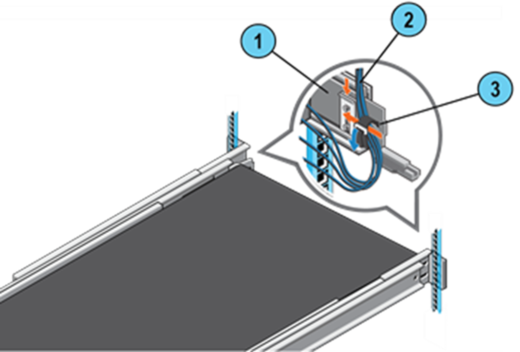
|
Item |
Description |
|---|---|
|
1 |
Inner CMA bracket (2) |
|
2 |
Cables |
|
3 |
Hook-and-loop strap (2) |


