Front Panel
This section describes the Front Panel on 1600 and 1800 Appliances - LEDs, ports, and buttons.
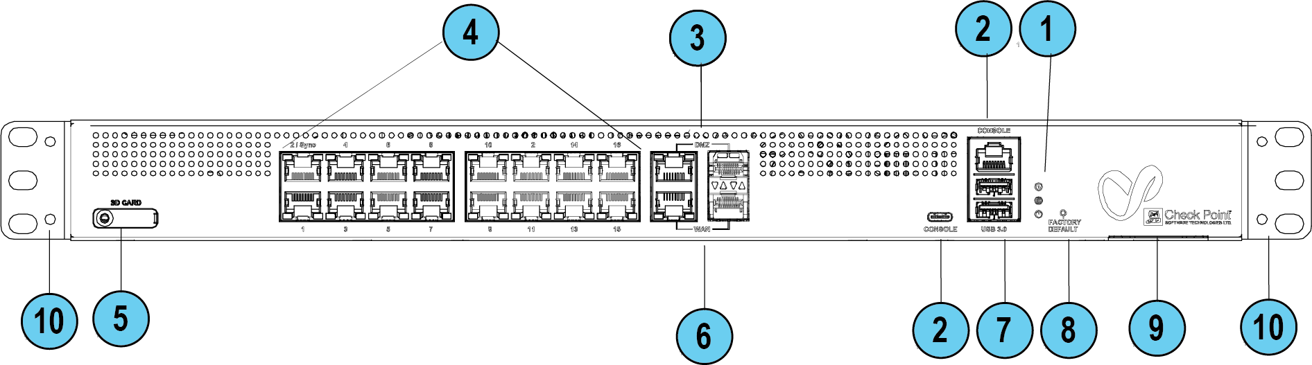
Front Panel on a 1600 Appliance
|
|
Note - There is only one set of LEDs. These LEDs show different colors depending on what activity is occurring. |

|
Key |
Item |
Description |
||||||
|---|---|---|---|---|---|---|---|---|
|
1 |
LEDs |
From top to bottom:
|
||||||
|
2 |
Console |
There are two console ports for the serial console cable: USB Type-C and RJ45. USB Type-C has priority when both are connected. Baud rate: 115200 |
||||||
|
3 |
DMZ ports |
The DMZ is a combo port of fiber SFP and RJ45 (on the right). Only one can operate a time when plugged in and connected. The RJ45 port supports 10 / 100 MbE and 1 GbE. The SFP port supports only 1 GbE.
|
||||||
|
4 |
LAN ports |
LAN ports 1-16. Support 10 / 100 MbE and 1 GbE. LAN 1 and LAN 2 (Sync in a cluster) also support 2.5 GbE. |
||||||
|
5 |
SD card slot |
Insert micro-SD card here. |
||||||
|
6 |
WAN ports |
Two WAN ports, each of which is a combo port of SFP and RJ45 (on the right). Only one can operate a time when plugged in and connected. The RJ45 port supports 10 / 100 MbE and 1 GbE. The SFP port supports only 1 GbE.
|
||||||
|
7 |
USB 3.0 (Type-A) |
Two USB ports 3.0 for software download. |
||||||
|
8 |
Factory Default |
Press the button continuously for 12 seconds to restore the appliance to its factory default. All user parameters previously configured are removed. |
||||||
|
9 |
Service tag |
Shows the regulated module, serial number, and the MAC address. |
||||||
|
10 |
Side brackets |
For rack mount. |


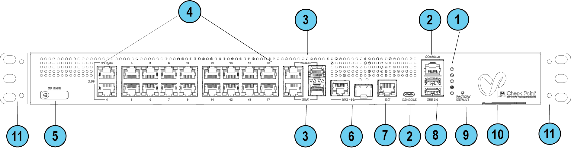
Front Panel on a 1800 Appliance
Note - There is only one set of LEDs. These LEDs show different colors depending on what activity is occurring.
|
Key |
Item |
Description |
||||||||||
|---|---|---|---|---|---|---|---|---|---|---|---|---|
|
1 |
LEDs |
From top to bottom:
|
||||||||||
|
2 |
Console |
There are two console ports for the serial console cable: USB Type-C and RJ45. USB Type-C has priority when both are connected. Baud rate: 115200. |
||||||||||
|
3 |
DMZ ports |
The DMZ is a combo port of fiber SFP and RJ45 (on the right). Only one can operate a time once plugged in and connected. The RJ45 port supports 10 / 100 MbE and 1 / 2.5 / 5 / 10 GbE. The SFP port supports only 10 GbE.
|
||||||||||
|
4 |
LAN ports |
LAN ports 1-18. Support 10 / 100 MbE and 1 GbE. LAN 1 and LAN 2 (Sync in a cluster) also support 2.5 GbE. |
||||||||||
|
5 |
SD card slot |
Insert micro-SD card here. |
||||||||||
|
6 |
WAN and WAN-B ports |
Two WAN ports each of which is a combo port of SFP and RJ45 (on the right). Only one can operate a time once plugged in and connected. The RJ45 port supports 10 / 100 MbE and 1 / 2.5 / 5 / 10 GbE. The SFP port supports only 1 GbE.
|
||||||||||
|
7 |
EXT port |
Management port. Supports 10 / 100 MbE and 1 GbE. |
||||||||||
|
8 |
USB3.0 |
USB port 3.0 for software download. |
||||||||||
|
9 |
Factory Default |
Press the button continuously for 12 seconds to restore the appliance to its factory default. All user parameters previously configured are removed. |
||||||||||
|
10 |
Service tag |
Shows the regulated module, serial number, and the MAC address. |
||||||||||
|
11 |
Side brackets |
For rack mount. |


Management LED
The Management LED shows the status of the retries mechanism:
|
Action |
Management LED Activity |
|---|---|
|
Zero Touch is running. |
Blinks red (slowly) |
|
Successfully connected to Zero Touch Cloud Server and saved the deployment script. |
Blinks red (rapidly) |
|
Zero Touch process is completed. SMP activation is not needed. |
Off |
|
Activation sleeping time. |
Blinks blue (slowly) |
|
Reactivation. |
Blinks blue (rapidly) |
|
SMP is connected. |
Solid blue |
|
SMP mode is off. |
off |
|
Gateway failed to connect to the SMP and will exit from the retry script. |
Solid red |
Wait times before retry:
|
Failure |
Waiting Time |
|---|---|
|
1st |
2 minutes |
|
2nd |
4 minutes |
|
3rd |
8 minutes |
|
4th |
16 minutes |
|
Subsequent |
Retries every 16 minutes until Cloud Services are successfully activated |
Network LEDs
The table below describes the network LEDs (RJ45 WAN and LAN ports and the SFP).
Each port uses a bi-color LED (green/amber) to reflect the link/activity and speed.
This also applies to the DMZ port of the 1600 appliance.
For 1800 appliances only:
2xRJ45 2.5GbE ports
Two bi-color (green and amber) LEDs per ports
|
2.5GbE RJ45 |
Link/Act LED #1 (bi-color) |
Speed LED #2 (bi-color) |
||
|---|---|---|---|---|
|
|
Green |
Amber |
Green |
Amber |
|
No link |
Off |
Off |
Off |
Off |
|
2.5G link |
On |
|
Off |
|
|
2.5G Act |
Blink |
|
Off |
|
|
1G link |
|
On |
|
On |
|
1G Act |
|
Blink |
|
On |
|
100M link |
|
On |
|
Blink |
|
100M Act |
|
Blink |
|
Blink |
|
10M link |
|
On |
|
Off |
|
10M Act |
|
Blink |
|
Off |
RJ45 and SFP 10GbE port
|
10GbE RJ45 |
Link/Act LED1 (Bi-color) |
Speed LED2 (Bi-color) |
||
|---|---|---|---|---|
|
|
Green |
Amber |
Green |
Amber |
|
10G link |
On |
|
On |
|
|
10G Act |
Blink |
|
On |
|
|
5G link |
On |
|
Blink |
|
|
5G Act |
Blink |
|
Blink |
|