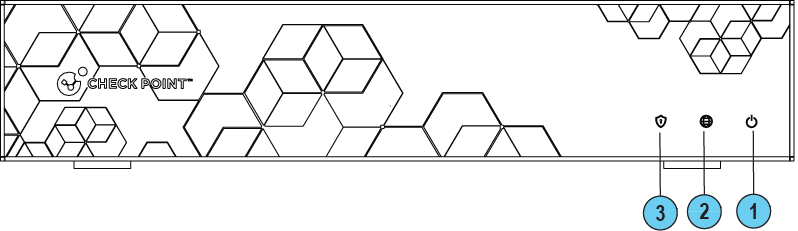
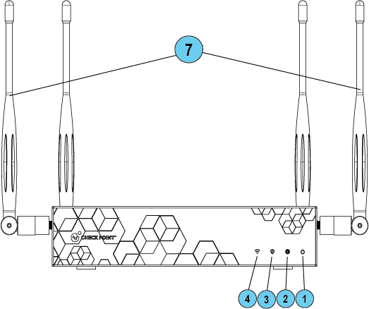
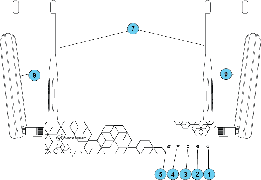
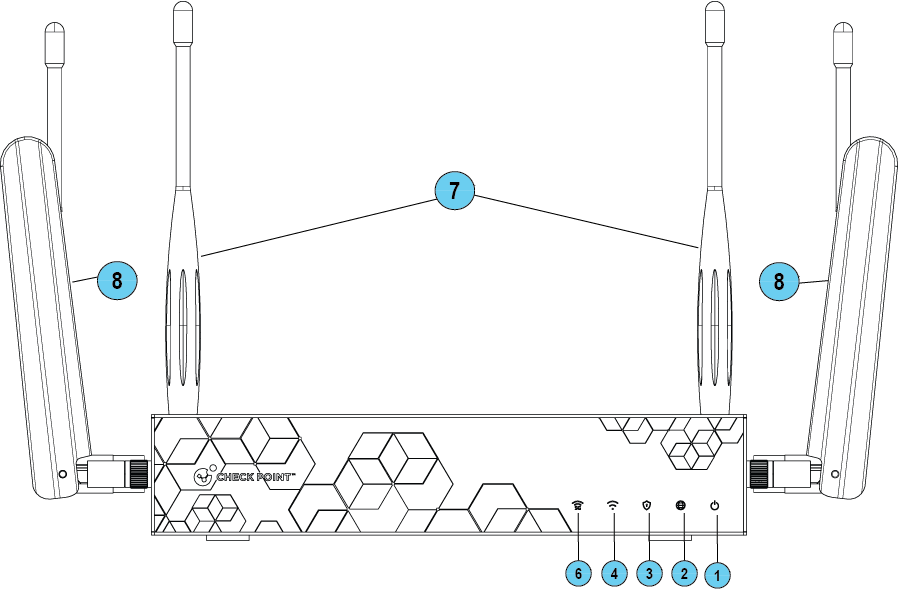
Front Panel
|
Wired |
WiFi |
|
|
|
|
WiFi-LTE |
WiFi-Cellular |
|
|
|
|
|
Note - There is only one set of LEDs. The LED color (blue / red / purple) depends on what activity occurs. |

|
Key |
Item |
LED |
Description |
||
|---|---|---|---|---|---|
|
1 |
Power LED |
|
|
||
|
2 |
Internet LED |
|
|
||
|
3 |
Management LED |
|
|
||
|
4 |
WiFi LED (WiFi models only) |
|
|
||
|
5 |
LTE LED (WiFi LTE model only) |
|
|
||
|
6 |
5G LED (WiFi Cellular model only) |
|
|

|
Key |
Item |
Description |
|---|---|---|
|
7 |
WiFi Antennas |
4 WiFi Antennas |
|
8 |
LTE Antennas |
2 LTE Antennas:
|
|
9 |
5G Antennas |
4 5G Antennas:
|
|
|
Best Practice - To improve the speed and reliability of the Cellular communication link, attach all four Cellular antennas. |

|
|
Notes:
|
Management LED
The Management LED shows the status of the retries mechanism:
|
Action |
Management LED Activity |
|---|---|
|
Zero Touch is running. |
Blinks red (slowly) |
|
Successfully connected to Zero Touch Cloud Server and saved the deployment script. |
Blinks red (rapidly) |
|
Zero Touch process is completed. SMP activation is not needed. |
LED off |
|
Activation sleeping time. |
Blinks blue (slowly) |
|
Reactivation. |
Blinks blue (rapidly) |
|
SMP is connected. |
Solid blue. |
|
SMP mode is off. |
LED off |
|
Gateway failed to connect to the SMP and will exit from the retry script. |
Constant red. |
Wait times before retry:
|
Failure |
Waiting Time |
|---|---|
|
1st |
2 minutes |
|
2nd |
4 minutes |
|
3rd |
8 minutes |
|
4th |
16 minutes |
|
Subsequent |
Retries every 16 minutes until Cloud Services are successfully activated |
Network LEDs
The table below describes the network LEDs (RJ45 WAN and LAN ports and the SFP).
Each port uses a bi-color LED to reflect the link/activity and speed, from 10M to 1GbE.
|
RJ45 and 1G SFP |
LED1 (Green) |
LED2 (Amber) |
|---|---|---|
|
No link |
Off |
Off |
|
1G link |
On |
On |
|
1G Act |
Blink |
On |
|
100M link |
On |
Off |
|
100M Act |
Blink |
Off |
|
10M link |
On |
Off |
|
10M Act |
Blink |
Off |