
Setting up the 1575R Appliance
-
Remove the Quantum Spark 1575R appliance from the shipping carton and place it on a tabletop.
For other mounting options, see below.
-
Identify the network interface marked as LAN1. This interface is pre-configured with the IP address
192.168.1.1.
Using the default SSID for a WiFi connection:
|
|
Note - This option is only available:
|
-
Connect the appliance cable and the WAN cable.
-
Use the SSID and password printed on the appliance sticker to connect to WiFi.

Note - Skip this step if connecting through LAN.
-
Browse to the default gateway IP address: https://192.168.1.1:4434
The Welcome screen of the First Time Configuration Wizard appears.
-
Click Fetch Settings from the Cloud.
-
In the new window, click Yes to confirm that you want to proceed.
-
The Internet connection page of the First Time Configuration Wizard
-
From the Connection type drop-down menu, select Static IP.
-
Click Connect.
The One Touch status bar starts to run.
|
|
Note - If you were connected to WiFi: After the One Touch script finishes running, the WiFi network you were connected to is deleted. As a result, you are disconnected from the appliance. |
Mounting Options
-
Desktop - No special hardware or mounting instructions necessary. Assemble the 4 rubber feet (as part of the box accessory kit) on the marked locations on the bottom side of the 1575R Appliance.
-
DIN rail kit (complies with IEC61850-3 class 0) as part of the box accessory kit – Attaches to either back panel (for 1575R Wired) or bottom panel (for 1575R Wired and Wired-LTE).
The DIN rail is supported on the bottom side for both flavors and on the rear side for the 1575R wired flavor.
-
Wall mount - Attached from bottom panel. Use the sticker included in the box and the 2 screws and anchors. (as part of the box accessory kit).
-
Wall mount brackets (comply with IEC60068-2-27, severity level 30g/11ms, IEC61850-3 Class 2) - 2 side brackets from the bottom side of the 1575R (Wired and WiFi-LTE). It is sold separately as a FRU.
Note - For Maritime installations, use only the wall mount brackets.
This table presents the dimensions of the 1575R Appliance with the DIN adapter of the Wired and Wireless. Use this to design the required space for the appliance.
|
Appliance Model |
Flavor |
Height (mm) |
Width (mm) |
Depth (mm) |
Notes |
|---|---|---|---|---|---|
|
1575R |
Wired |
90 |
150 |
150 |
Without rubber feet |
|
1575R with rear DIN adapter |
90 |
150 |
168 |
|
|
|
1575R with bottom DIN adapter |
108 |
150 |
150 |
|
|
|
1575RWL with rear DIN adapter |
WiFi-LTE |
177 |
150 |
225 |
Includes the LTE and WiFi antennas. For this setup, a middle-part adapter is required between the DIN adapter and the 1575R Appliance. |
|
1575RWL with bottom DIN adapter |
195 |
150 |
225 |
Includes the LTE and WiFi antennas. |
To mount the appliance using the DIN rail kit:
Attach the DIN rail kit with the 4 M3 screws provided in the box. Depending on the model, the DIN rail mount holes may be located on the back panel or bottom panel or both.
Back panel


Bottom of the appliance
In the 1575R WiFi-LTE model, use the DIN rail mount holes located on the bottom panel:

To mount the appliance to the wall (standard):
-
Place the wall-mount sticker on the wall and drill two holes for the screws. Make sure the holes are aligned with the sticker's markings.
-
Insert the screw anchors into the holes drilled in the wall.
-
Attach the 2 screws in the accessory kit (M4*6) to the wall.
-
Mount the appliance and verify the 2 screws are fastened well to the appliance.
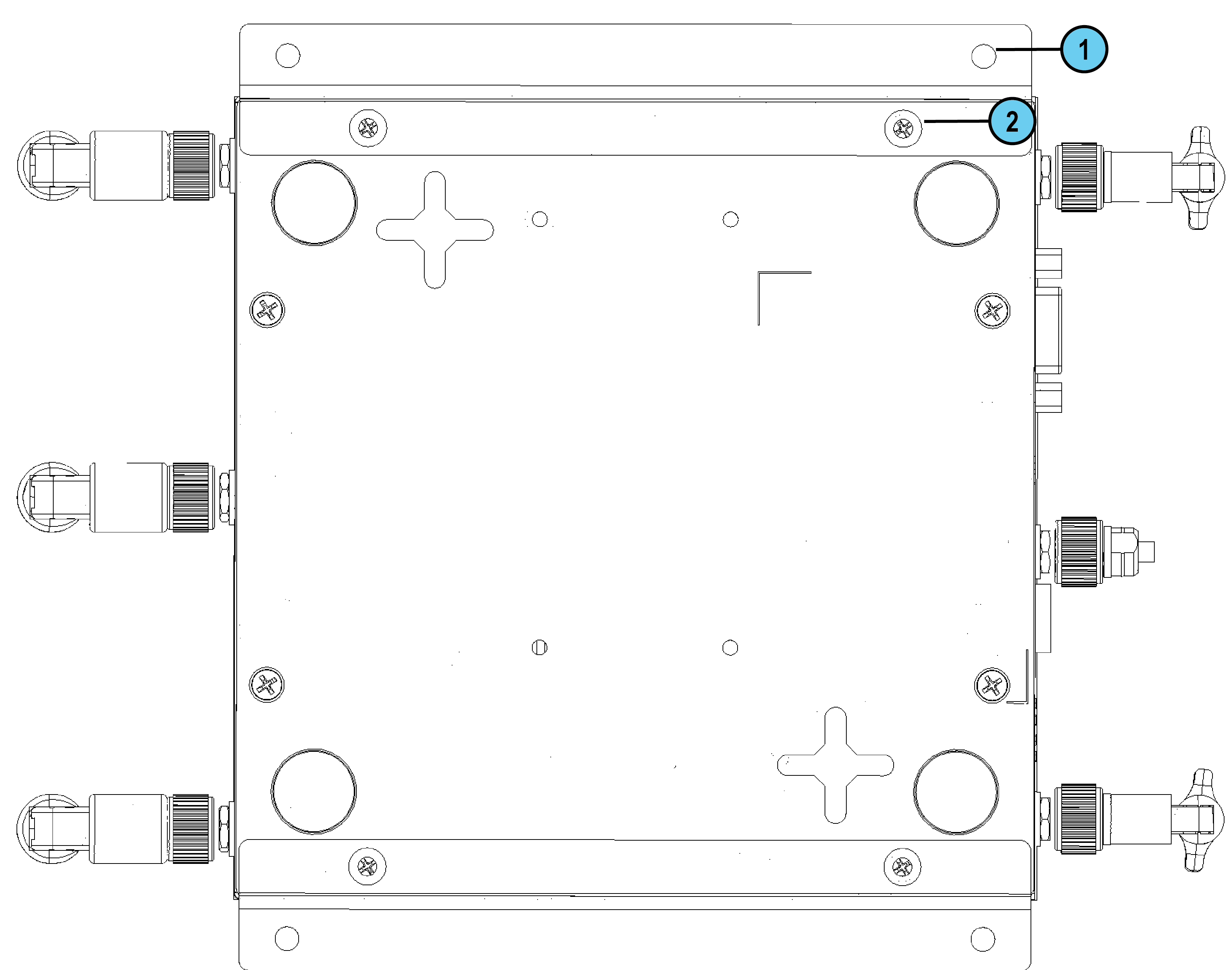
To mount the appliance to the wall (side brackets):
The side wall mount brackets are not part of the kit and are sold separately as an FRU.
-
Attach each bracket to the side of the 1575R appliance. Use 2 screws for each bracket. (#2 on the diagram)
-
Use the holes on the bracket (#1 on the diagram) to mark the screw placement on the wall or surface. Insert a screw through each hole and make sure the appliance is securely fastened.