Setting up the Appliance
-
Remove the Quantum Spark 1595R appliance from the shipping carton and place it on a tabletop.
For other mounting options, see below.
-
Identify the network interface marked as LAN1. This interface is pre-configured with the IP address
192.168.1.1.
Mounting Options
-
Desktop - No special hardware or mounting instructions necessary. Assemble the 4 rubber feet (as part of the box accessory kit) on the marked locations on the bottom side of the 1570R Appliance.
-
DIN rail kit (complies with XXX 0) as part of the box accessory kit – Attaches to either back panel (for 1595R Wired) or bottom panel (for 1595R Wired and Wired-Cellular).
The DIN rail is supported on the bottom side for both flavors and on the rear side for the 1595R wired flavor.
-
Wall mount - Attached from bottom panel. Use the sticker included in the box and the 2 screws and anchors. (as part of the box accessory kit).
-
Wall mount brackets (comply with IEC60068-2-27, severity level 30g/11ms, IEC61850-3 Class 2) - 2 side brackets from the bottom side of the 1595R (Wired and WiFi-Cellular). It is sold separately as a FRU.

Note - For Maritime installations, use only the wall mount brackets.
This table presents the dimensions of the 1595R Appliance with the DIN adapter of the Wired and Wireless. Use this to design the required space for the appliance.
|
|
Flavor |
Height (mm) |
Width (mm) |
Depth (mm) |
Notes |
|---|---|---|---|---|---|
|
1595R |
Wired |
41.30 |
170 |
150 |
Without rubber feet |
|
1595R with rear DIN adapter |
41.30 |
170 |
168 |
|
|
|
1595R with bottom DIN adapter |
108 |
170 |
150 |
|
|
|
1570WLE with rear DIN adapter |
WiFi-LTE |
177 |
150 |
225 |
Includes the LTE and WiFi antennas. For that setup, a middle-part adapter is required between the DIN adapter and the 1595R Appliance. |
|
1570WLE with bottom DIN adapter |
195 |
150 |
225 |
Includes the LTE and WiFi antennas. |
To mount the appliance using the DIN rail kit:
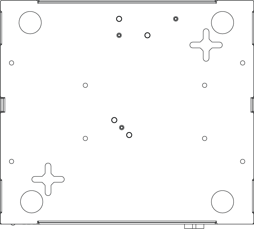
Attach the DIN rail kit with the 4 M3 screws which came in the box. Depending on the model, the DIN rail mount holes are located on the back panel or bottom panel or both.
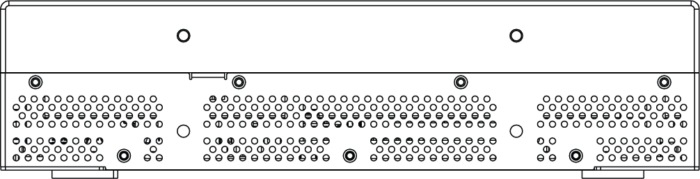
Back panel
Bottom of the appliance
In the 1595R model, use the DIN rail mount holes located on the bottom panel :
|
Cellular |
Wired |
|---|---|
|
|
|


To mount the appliance to the wall (standard):
-
Place the wall-mount sticker on the wall and drill two holes for the screws.
-
Insert the screw anchors into the wall.
-
Attach the 2 screws in the accessory kit (M4*6) to the wall.
-
Mount the appliance and verify the 2 screws are fastened well to the appliance.
To mount the appliance to the wall (side brackets):
The side wall mount brackets are not part of the kit and are sold separately as an FRU.

|
Cellular |
Wired |
|---|---|
|
|
|


-
Attach each bracket to the side of the 1595R appliance. Use 2 screws for each bracket. (#2 on the diagram)
-
Use the holes on the bracket (#1 on the top diagram) to mark the screw placement on the wall or surface. Insert a screw through each hole and make sure the appliance is securely fastened.