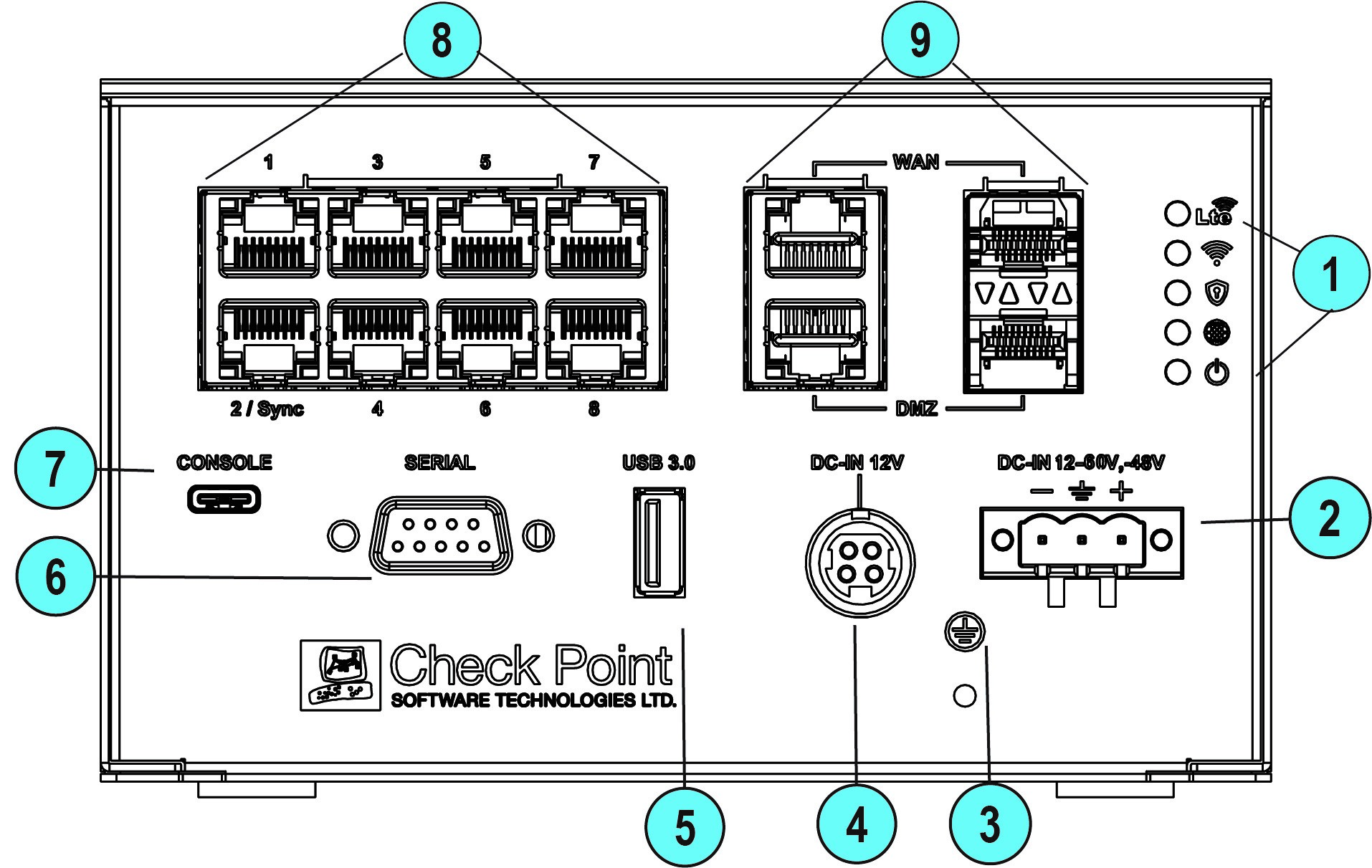
Front Panel
Wired
|
|
Note - The Tower LEDs reflect the system status. The 5 LEDs are bi-color (blue and red). |

|
Key |
Item |
Description |
||||||||||
|---|---|---|---|---|---|---|---|---|---|---|---|---|
|
1 |
LEDs |
From top to bottom:
|
||||||||||
|
2 |
12-60V, - 48VDC input |
Connects to the power source cable from your power infrastructure. |
||||||||||
|
3 |
Ground screw |
Protective earthing terminal. |
||||||||||
|
4 |
Power cord socket |
Plug the power adapter cord in here. Use only Check Point power adapters. |
||||||||||
|
5 |
USB port 3.0 (Type-A) |
USB port 3.0 for software download. |
||||||||||
|
6 |
Serial port |
Plug in the serial cable here (standard DB9). |
||||||||||
|
7 |
Console |
Plug in the USB (Type-C) serial console cable here. Baud rate: 115200. |
||||||||||
|
8 |
LAN ports |
LAN ports 1-8. Port #2 is Sync in a cluster. Support 10 / 100 MbE and 1 GbE. |
||||||||||
|
9 |
WAN and DMZ ports |
WAN and DMZ ports support copper RJ45 and fiber interface types. The RJ45 port supports 10 / 100 MbE and 1 GbE. The SFP port supports only 1 GbE.
|


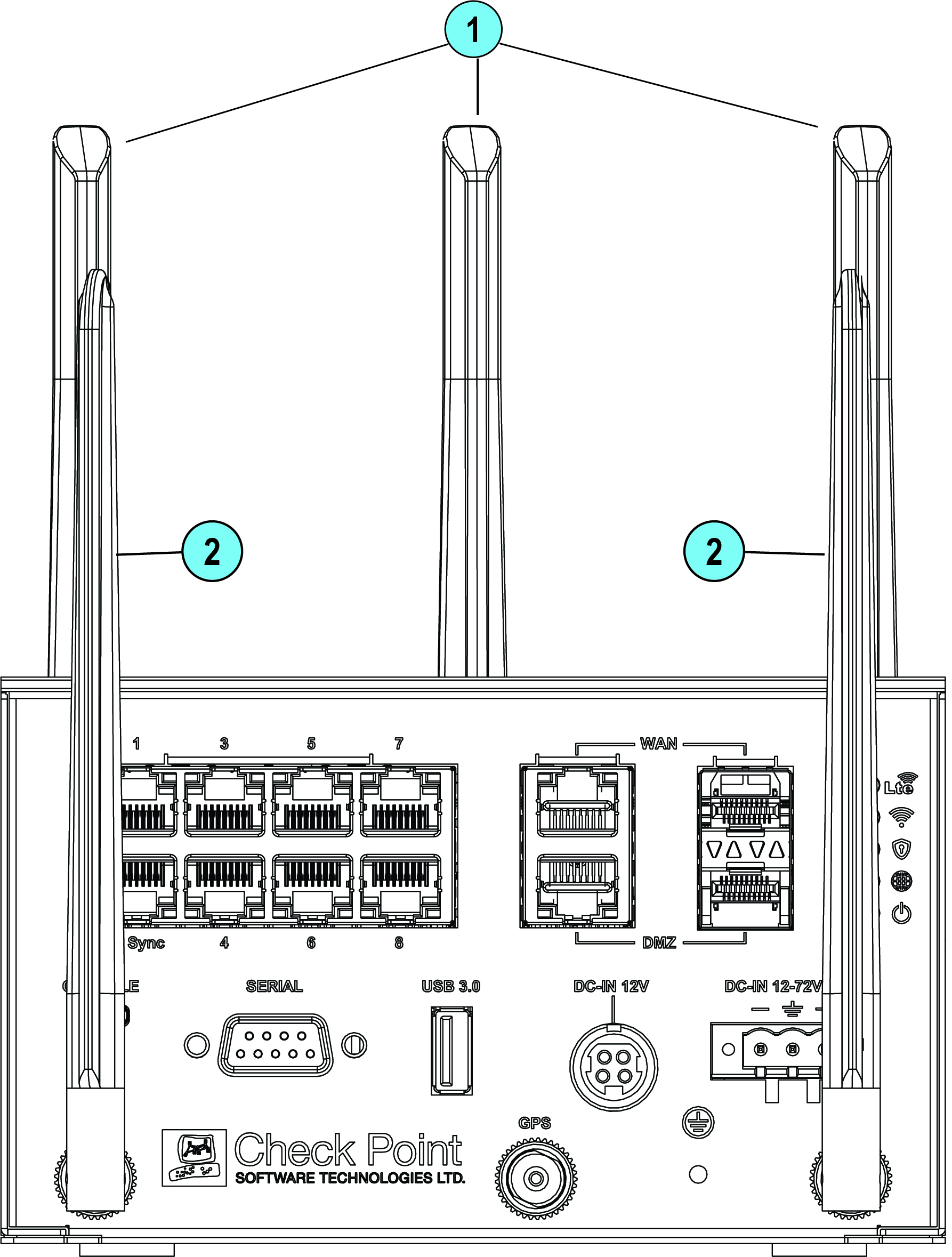
WiFi-LTE
|
|
Note - LEDs and ports are identical on Wired + WiFi-LTE models. |
|
Key |
Item |
Description |
|---|---|---|
|
1 |
WiFi Antennas |
3 WiFi Antennas |
|
2 |
LTE Antennas |
2 LTE Antennas:
|
|
|
Best Practice -To improve the speed and reliability of the LTE communication link, attach the second LTE antenna (Aux). |

-
You must attach all provided WiFi antennas to the appliance.
-
Many mobile carriers require a minimum Total Radiated Power (TRP), which requires an efficient antenna. Make sure the product outputs sufficient power to meet the TRP minimum but does not exceed the FCC and IC EIRP limits.
Management LED
|
|
Notes:
|
The Management LED shows the status of the retries mechanism:
|
Action |
Management LED Activity |
|---|---|
|
Zero Touch is running. |
Blinks red (slowly) |
|
Successfully connected to Zero Touch Cloud Server and saved the deployment script. |
Blinks red (rapidly) |
|
Zero Touch process is completed. SMP activation is not needed. |
Off |
|
Activation sleeping time. |
Blinks blue (slowly) |
|
Reactivation. |
Blinks blue (rapidly) |
|
SMP is connected. |
Solid blue |
|
SMP mode is off. |
Off |
|
Gateway failed to connect to the SMP and will exit from the retry script. |
Solid red |
Wait times before retry:
|
Failure |
Waiting Time |
|---|---|
|
1st |
2 minutes |
|
2nd |
4 minutes |
|
3rd |
8 minutes |
|
4th |
16 minutes |
|
Subsequent |
Retries every 16 minutes until Cloud Services are successfully activated |
Network LEDs
The table below describes the network LEDs (RJ45 WAN and LAN ports and the SFP).
Each port uses a bi-color LED to reflect the link/activity and speed.
The SFP port supports only 1GbE.