Smart-1 7000-L Appliance Hardware
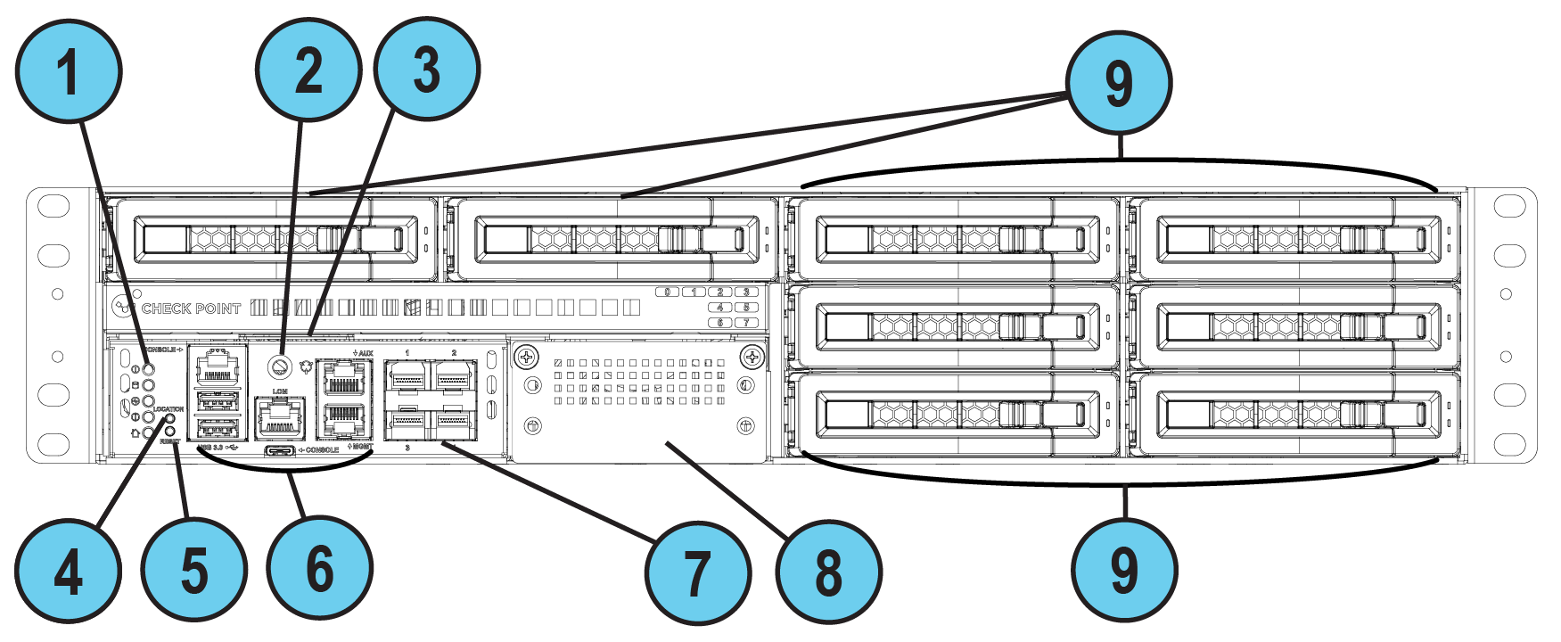
Front Panel
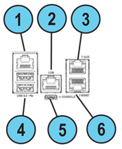
Front Panel Ports
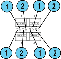
Front Panel 1G Port LEDs

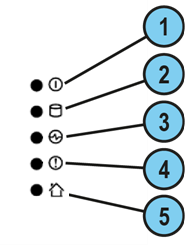
Front Panel System LEDs
|
Item |
Icon |
Component |
Description |
|---|---|---|---|
|
1 |
|
System power |
|
|
2 |
|
Storage device activity |
|
|
3 |
|
Power supply status |
|
|
4 |
|
Alert |
|
|
5 |
|
Location beacon |
You can turn on / off the Location Beacon LED in these ways:
|


Front Panel On-board Port LEDs
Each pair of LEDs are associated with a port.
-
LEDs 1 and 2 that point up are associated with the port located above them (ports labeled 1 and 2 on the chassis).
-
LEDs 1 and 2 that point down are associated with the port located below them (ports labeled 3 and 4 on the chassis).
|
Item |
Component |
Description |
|---|---|---|
|
1 |
Port activity LED |
|
|
2 |
Link Speed LED |
|
|
Item |
Component |
Description |
|---|---|---|
|
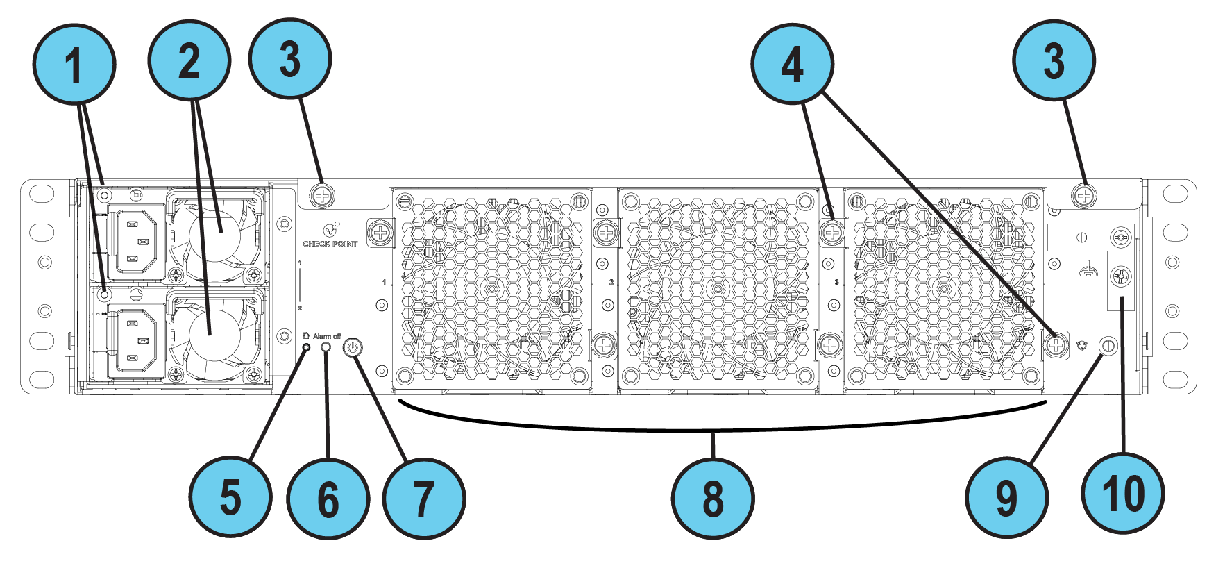
1 |
LED indicator for each AC power supply unit |
|
|
2 |
Power supply units |
Power supply units (PSUs) that you can hot swap. Each PSU connects to an electric outlet. You can use the cable restraints to avoid accidental removal of the power supply cable. The PSUs are numbered from top to bottom in the OS as "Power Supply #1" (top) and "Power Supply #2" (bottom). |
|
3 |
Cover screws |
Loosen screws to remove the cover of the appliance. |
|
4 |
Thumb screws for cooling fan unit |
Loosen screws to remove the cooling fan unit from the appliance. |
|
5 |
Location LED |
Note - Turn off the Location beacon LED the same way you turned it on. |
|
6 |
Alarm Off button for power supply units |
An alarm sounds if:
Press this button to turn off the alarm. Note that this button is functional immediately after powering up the appliance. |
|
7 |
Main power button |
When the appliance is turned off, turns the appliance on. When the appliance is turned on, pressing and releasing the button starts an orderly shutdown process. Alternatively, holding the button for 4 seconds forces a machine shut down. |
|
8 |
Cooling fan units |
Units are numbered from right to left: When checking the hardware sensors in the CLI, they are referred to as " |
|
9 |
ESD grounding point |
When servicing the appliance, connect an ESD strap to this point. |
|
10 |
Metal grounding plate |
Used to connect the grounding lug. |
Grounding the Appliance
Before you start, make sure you have these items:
-
Two grounding screws (attached to the metal grounding plate).
-
A UL listed two-hole grounding lug, similar to Panduit LCD6-38D-L.
-
Copper grounding wire 6 AWG (the insulation color must be green and yellow to meet the IEC/UL 62368-1 CL5.6.2.2 requirement or the insulation color must comply with your local electrical regulations).
-
Grounding design that complies with the country or local electrical codes.
-
A wire crimping tool suitable for the grounding lug type.
-
A screwdriver suitable for the grounding screws.
Prerequisites:
-
Insert the grounding wire in the lug (connector).
-
Use the crimping tool to crimp the lug onto the grounding wire.
-
Place the screwdriver near the appliance rear panel.
-
Place the two grounding screws near the appliance rear panel.
Procedure:
-
On the appliance rear panel, locate the metal grounding plate (on the far right).
-
Attach the grounding lug to the grounding plate.
You can attach it vertically or horizontally.
-
Make sure the two holes in the grounding lug are aligned with the corresponding holes in the grounding plate.
-
Insert the first grounding screw through one of the holes in the grounding lug so it goes into the corresponding hole in the grounding plate.
-
Use a screwdriver to tighten the first screw (maximum torque of 6 kgf×cm).
-
Insert the second grounding screw through the second hole in the grounding lug so it goes into the corresponding hole in the grounding plate.
-
Use a screwdriver to tighten the second screw (maximum torque of 6 kgf×cm).
Cooling Fan Units Naming Convention
When you check the hardware sensors in the Gaia Portal or Gaia Clish, note that the cooling fans use a different naming convention.
Use this table to identify each of the 3 fans:
|
Gaia Portal |
CLI |
|---|---|
|
SYS_FAN1 - System Fan #1 |
SYS_FAN1 |
|
SYS_FAN2 - System Fan #2 |
SYS_FAN2 |
|
SYS_FAN3 - System Fan #3 |
SYS_FAN3 |
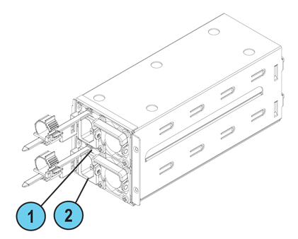
Installing the Power Cable Restraint
You can use the power cable restraint to prevent accidental removal of the power cable.

|
Item |
Description |
|---|---|
|
1 |
Restraint anchor |
|
2 |
Cable loop |
|
3 |
Restraint strip tab |
|
4 |
Restraint strip |
|
Item |
Description |
|---|---|
|
1 |
Restraint strip slot |
|
2 |
Power supply inlet |
To install the power cable restraint:
-
If a power cable is connected to the power supply inlet, disconnect it.
-
Find the restraint strip slot on top of the power supply inlet.
-
Make sure that the cable loop on the restraint faces the power supply inlet.
-
Insert the restraint strip anchor into the slot until it snaps and locks.
-
Connect the power cable to the power supply inlet.
-
Pull the restraint tab to the side to move the cable loop on the restraint strip.
-
Move the cable loop until you can wrap it around the power cable as shown in the next figure.
-
Insert the open side of the cable loop into the loop slot until it is tight against the power cable.
-
Make sure the cable loop is secured and the power cable cannot be removed.
Lights Out Management
The Check Point Lights Out Management (LOM) card lets you use a dedicated management channel to remotely control Check Point appliances. Lights Out Management can also work when the appliance is turned off or does not respond. However, the appliance must be connected to a power source.
For more information about Lights Out Management, see the Lights Out Management (LOM) HTML5-based Card Administration Guide.
Dual Redundant BIOS
To ensure resilience in the event of a BIOS failure, Smart-1 7000-L Appliances are equipped with dual redundant BIOS images.
If an appliance encounters a BIOS failure, it boots up from a recovery, read-only BIOS image that enables full functionality of the appliance.
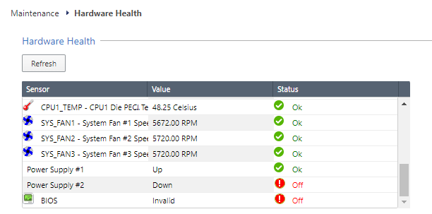
These notifications appear in the event of a BIOS failure:
-
The appliance's Alert LED on the front panel blinks red.
-
The Gaia Portal > Maintenance > Hardware Health page shows that the BIOS sensor is Invalid and its status is Off.
Example:
-
An SNMP trap message is sent (if the
biosFailuretrap was configured in the Gaia Portal or Gaia Clish).Example:

To recover from a BIOS failure, see sk108517 or contact Check Point Support. The appliance is fully functional until the BIOS recovery is completed. Note that it can take a few minutes for it to boot in BIOS recovery mode.
PSU Configuration and Monitoring
These are the supported PSU configurations for the Smart-1 7000-L appliance model and PSU types:
|
|
Important - All PSUs on an appliance must be of the same type: either all AC or all DC. |

When a PSU functions correctly:
-
The PSU LED is green
-
The Alert LED is not blinking due to a PSU issue (might still be blinking due to other errors)
-
There is no SNMP alarm.
When a PSU does not function correctly:
-
The PSU LED is amber
-
The Alert LED is blinking due to a PSU issue
-
An SNMP alarm is sent.
To monitor the PSUs in the CLI:
-
Connect to the command line on the appliance.
-
Log in to Gaia Clish.
-
Run:
show sysenv psExample output from a Smart-1 7000-L appliance:
Hardware Information

Name              Value   Unit      Type    Status   Maximum   Minimum
Power Supply #1   Up      Up/Down   Power   0        Up        Down
Power Supply #2   Up      Up/Down   Power   0        Up        Down
Where:
DC Power Connections
When your appliance uses a DC PSU, make sure to follow these instructions.
To connect DC power wires to a DC PSU connector:
-
Connect the GREEN wire to the ground.
-
Connect the RED wire to the 36-46/46-72 Volt pin on the DC power source.
-
Connect the BLACK wire to the return pin on the DC power source.

For further instructions, refer to the Installing and Removing DC Power Supply Units guide.
|
|
Important - This product is intended to be supplied by a UL Listed DC power source, rated 36-46/46-72Vdc, 35/40A minimum, Tmax=40°C, and the maximum altitude of operation=5000m. The wire requirements: 8 AWG, 40A minimum, 72V minimum. |
AC Power Cords
The supplied AC power cords are specific to the geographical region.
These are some of the available power cords.
|
Region |
Plug |
Connector |
Cable |
Diagram |
|---|---|---|---|---|
|
EU |
QP-004, 16A 250V~ |
QP-007, 10A 250V~ |
HO5VV-F 3G 0.75mm2 |
|
|
Australia |
QP-003, 10A 250V~ |
QP-007, 10A 250V~ |
HO5VV-F 3G 0.75mm2 |
|
|
UK |
QP-026, 10A 250V~ |
QP-007, 10A 250V~ |
HO5VV-F 3G 0.75mm2 |
|
|
US |
QP-02, 10A 125V~ |
QP-007, 10A 125V~ |
SJT 18AWG 3C 105oC |
|
|
US |
QP-02, 15A 125V~ |
QP-007, 15A 125V~ |
SJT 14AWG 3C 105oC |
|
|
US |
QP-055, 15A 125V~ |
QP-007, 15A 125V~ |
SJT 14AWG 3C 105oC |
|
|
Japan |
QP-005, 10A 250V~ |
QP-007, 10A 250V~ |
HO5VV-F 3G 0.75mm2 |
|
|
India |
QP-013, 16A 250V~ |
QP-007, 10A 250V~ |
3INR 3G 0.75mm2 |
|
|
China |
QP-012, 10A 250V~ |
QP-007, 10A 250V~ |
VCTF 3G 2mm2 |
|
|
Israel |
QP-029R, 16A 250V~ |
QP-007, 10A 250V~ |
HO5VV-F 3G 0.75mm2 |
|
|
South Africa |
YP-80, 16A 250V~ |
QP-007, 10A 250V~ |
HO5VV-F 3G 0.75mm2 |
|
|
Argentina |
QP-048, 10A 250V~ |
QP-007, 10A 250V~ |
HO5VV-F 3G 0.75mm2 |
|


Replacing and Upgrading Components
The appliances have parts that you can easily replace to minimize downtime.
There are also components that you can install to upgrade the appliance.
These parts and components can be used with the appliance:
-
Telescopic rails
-
Line cards
-
Transceivers
-
AC and DC power supply units
-
Storage devices
-
System memory
-
Cooling fan units
-
Lights Out Management
For more information about how to install these parts and components, see the appliance Home Page sk182601.
|
|
Warning - Unless directed to do so by Check Point Software Technologies Ltd., you are prohibited by warranty and support agreements to replace any parts. |
