Connecting DC Power to the 64000 Chassis
Connect the DC PEMs in the Chassis to an external battery power source.
You must have a mains DC power supply system that includes batteries and a branch circuit breaker of 50A for each terminal block (250A in total) for each DC PEM.
The DC PEM is described in DC Power Entry Modules (PEMs) for the 64000 Chassis.
For DC power redundancy, connect the two DC PEMs to two separate DC power sources.

|
Important - The two DC power sources must not connect one to the other. This is important to prevent excessive EMC radiation due to imbalance of the incoming and outgoing currents of each DC PEM. Specifically, do not connect the two DC PEMs to the same DC power source and do not connect the Return lines of the two DC PEMs. |
Required Tools and Parts:
-
10 DC wire leads for each DC PEM that connects to the DC power supply.
Use 6AWG wires. There is no standard for DC wire color coding. Use the color codes on the DC power source (battery) for the DC wire leads.
-
Wire cutter.
-
Wire stripper.
-
Screwdriver for tightening the screws in the Phoenix Contact PC 16/ 2-ST-10,16 (1967375) terminal connectors.
Wires and Lugs are not supplied by Check Point
To connect DC power:
Note - These instructions assume that you already installed the DC PEMs in the Chassis.
|
Step |
Instructions |
|---|---|
|
1 |
Set the branch circuit breakers at the mains to the "OFF" position. |
|
2 |
On each DC PEM, set all the circuit breakers to the "OFF" position. |
|
3 |
With the appropriate wire stripper, strip the ends of the wire leads you plan to attach to the terminal block pluggable connector. Stripping length is 7.5mm. |
|
4 |
Insert the stripped end of the plus wire lead into the leftmost contact of the terminal block pluggable connector. With an appropriate screwdriver, tighten the screw clamp. |
|
5 |
Insert the stripped end of the minus wire lead into the rightmost contact of the terminal block pluggable connector. With an appropriate screwdriver, tighten the screw clamp. |
|
6 |
Plug the terminal connector into its terminal block socket on each DC PEM. Repeat Steps 3 - 6 for the remaining terminal blocks on each DC PEM. |
|
7 |
Set the branch circuit breakers at the mains to the ON position. |
|
8 |
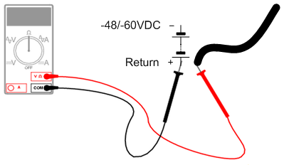
Use a multimeter to make sure the polarity and the range of the DC voltage are correct. Use a multimeter to measure the resistance between the disconnected DC PEM wire leads and the Battery's Return terminal. For all the DC PEM wire leads, one at a time:
|
|
9 |
On each DC PEM, set all the circuit breakers to the "ON" position. |
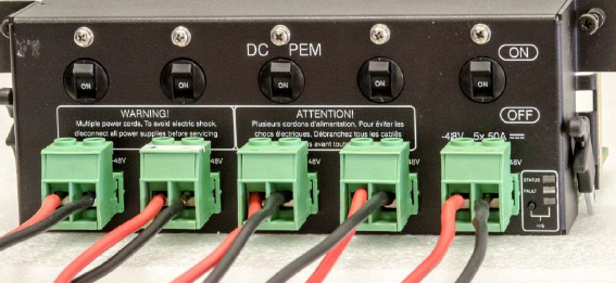
DC PEM with wires connected to the terminal connectors: