Step 2: Installing the Chassis in a Rack

|
Important - Before you mount the Chassis in the rack, attach the rear static grounding screws to the Chassis. |
Installing the Chassis in a Rack
-
Put the Chassis in front of the rack, in the center of the rack.
-
Lift and slide the Chassis onto the rack shelf.
-
Make sure that the holes in the front mounting flanges of the Chassis align with the holes in the rack rails.
-
Insert mounting screws into the front mounting flanges aligned with the rack.
-
Secure the appliance by fastening the mounting screws to the rack.
The Chassis must be leveled, and not positioned at an angle.
-
Attach grounding cables to the grounding screws on the Chassis.

|
Caution - The intra-building ports (Ethernet and serial) of the equipment or subassembly are suitable for connection to intra-building or unexposed wiring or cabling only. The intra-building ports of the equipment or subassembly must not be connected metallically to interfaces that connect to the outside plant (OSP) or its wiring. These interfaces are designed for use as intra-building interfaces only (Type 2 or Type 4 ports as described in GR-1089-CORE) and require isolation from the exposed OSP cabling. The addition of primary protectors is not sufficient protection in order to connect these interfaces metallically to OSP wiring. |
Grounding the Chassis
Background:
-
The Chassis is suitable for installation as part f the Common Bonding Network (CBN).
-
You can install the 64000 Chassis in network telecommunication facilities or locations, where the National Electric Code applies.
-
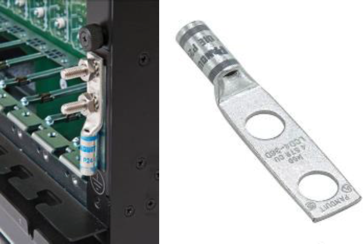
The Chassis includes a two-hole grounding lug, Panduit LCD1-38D-E. Use one AWG grounding cable with this lug.
-
Grounding design must comply with the country or local electrical codes.
In the United States, grounding must comply with Article 250 of the NEC unless superseded by local codes.
-
Ground connection is essential before connecting the power supply.
-
There must be an uninterruptable safety earth ground from the main power source to the Chassis.
In case the grounding connection fails, disconnect the power cord from the Chassis until the ground is restored.
-
To avoid the potential for an electrical shock hazard, the safety-grounding conductor must be determined based on the feed current rating and cable length.
Procedure:
-
On the rear of the Chassis, locate the grounding connection on the right.
-
Using the appropriate wrench, unfasten the two nuts and remove the lug.
-
Crimp the 1 AWG wire to the lug.
-
Return the lug to its place on the rear-right of the Chassis and refasten the nuts.
The maximum applied torque of the nuts is 35 lbf*in (4 N*m).
-
Connect the ground wire to the appropriate ground connection of the building infrastructure.