9000 Appliances Hardware
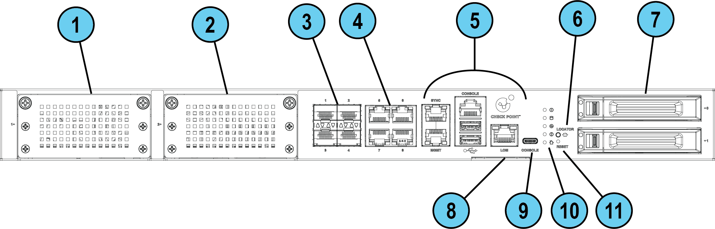
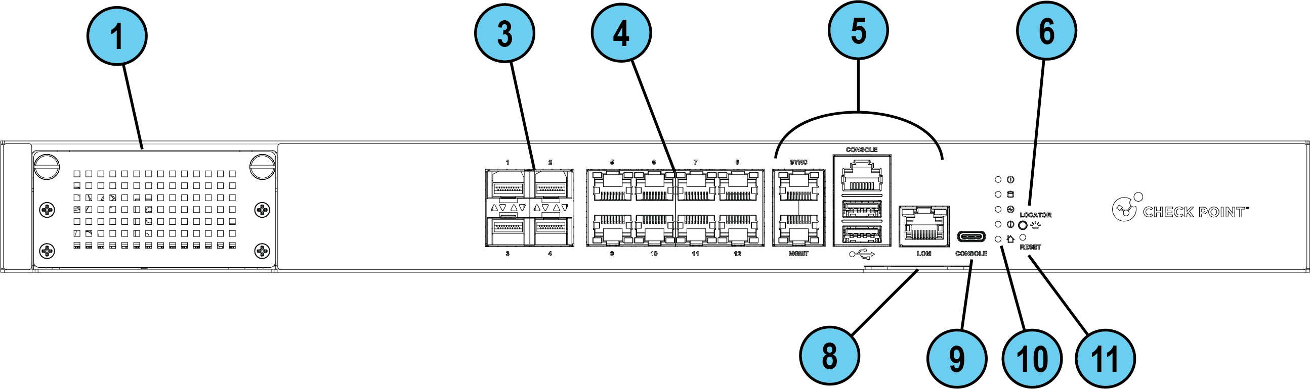
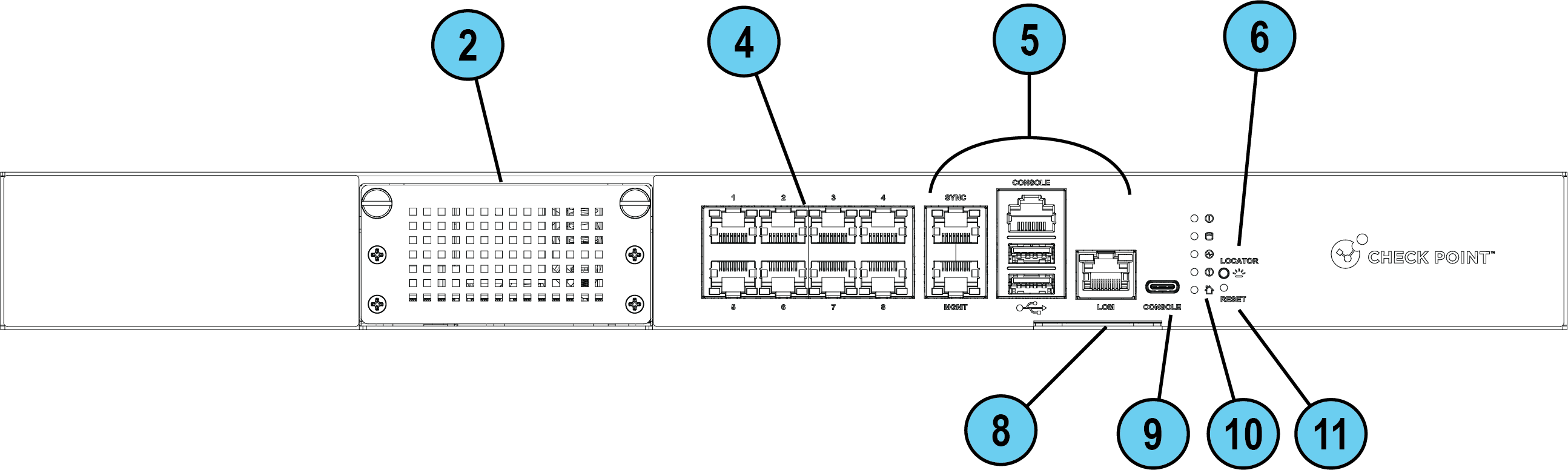
Front Panel

|
Item |
Component |
Description |
||
|---|---|---|---|---|
|
1 |
Expansion line card |
In the Gaia OS on the 9800 / 9700 / 9400 / 9300 appliance, the ports on this expansion line card are assigned the names Port speeds for supported line cards on the 9800 / 9700 / 9400 appliances are: 1/10/25/40/100G Port speeds for supported line cards on the 9300 appliance are: 1/10/25G |
||
|
2 |
Expansion line card |
In the Gaia OS on the 9800 / 9700 appliance, the ports on this expansion line card are assigned the names Port speeds for supported line cards on the 9800 / 9700 appliances are: 1/10/25/40/100G In the Gaia OS on the 9200 / 9100 appliance, the ports on this expansion line card are assigned the names Port speeds for supported line cards on the 9200 / 9100 appliances are: 1/10/25G |
||
|
3 |
On-Board 1/10G Fiber ports |
In the Gaia OS on the 9800 / 9700 / 9400 appliance, these ports are assigned the names from
|
||
|
4 |
On-Board RJ45 1G ports |
In the Gaia OS on the 9800 / 9700 appliance, these ports are assigned the names from In the Gaia OS on the 9400 appliance, these ports are assigned the names from In the Gaia OS on the 9300 / 9200 / 9100 appliance, these ports are assigned the names from
|
||
|
5 |
Appliance ports |
See Front Panel Ports - Use these ports to connect to the appliance. | ||
|
6 |
Locator button |
Turns the location beacon LED on and off in the appliance. |
||
|
7 |
2 Storage devices |
In 9700 / 9800 appliances:
|
||
|
8 |
A slide-out card that identifies the appliance and shows its serial number and MAC address. |
|||
|
9 |
Console port |
A USB Type-C port for a serial connection to the appliance. |
||
|
10 |
System LEDs |
|||
|
11 |
Reset |
Insert a pin for 5 to 8 seconds to perform a hardware reset. |

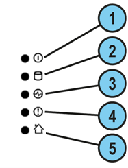
Front Panel Ports

|
Item |
Icon |
Component |
Description |
|---|---|---|---|
|
1 |
|
System power |
|
|
2 |
|
Storage device activity |
|
|
3 |
|
Power supply status |
|
|
4 |
|
Alert |
|
|
5 |
|
Location beacon |
You can turn on / off the Location Beacon LED in these ways:
|


Grounding the Appliance
Before you start, make sure you have these items:
-
Two grounding screws (marked in a bag labeled GND Screws (2) in the Assembly Kit bag).
-
A UL listed two-hole grounding lug, similar to Panduit LCD6-38D-L.
-
Copper grounding wire 6 AWG (the insulation color must be green and yellow to meet the IEC/UL 62368-1 CL5.6.2.2 requirement or the insulation color must comply with your local electrical regulations).
-
Grounding design that complies with the country or local electrical codes.
-
A wire crimping tool suitable for the grounding lug type.
-
A screwdriver suitable for the grounding screws.
Prerequisites:
-
Insert the grounding wire in the lug (connector).
-
Use the crimping tool to crimp the lug onto the grounding wire.
-
Place the screwdriver near the appliance rear panel.
-
Place the two grounding screws near the appliance rear panel.
Procedure:
-
On the appliance rear panel, locate the metal grounding plate (on the far right).
-
Attach the grounding lug to the grounding plate.
You can attach it vertically or horizontally.
-
Make sure the two holes in the grounding lug are aligned with the corresponding holes in the grounding plate.
-
Insert the first grounding screw through one of the holes in the grounding lug so it goes into the corresponding hole in the grounding plate.
-
Use a screwdriver to tighten the first screw (maximum torque of 6 kgf×cm).
-
Insert the second grounding screw through the second hole in the grounding lug so it goes into the corresponding hole in the grounding plate.
-
Use a screwdriver to tighten the second screw (maximum torque of 6 kgf×cm).
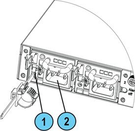
Installing the Power Cable Restraint
You can use the power cable restraint to prevent accidental removal of the power cable:
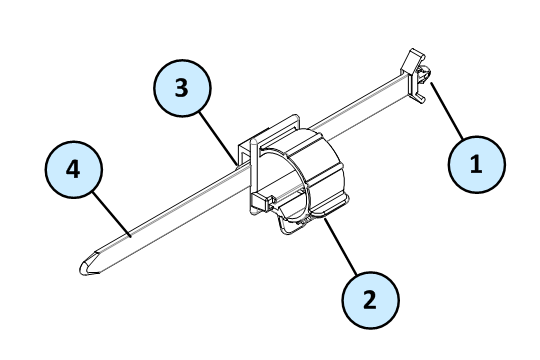
|
Item |
Description |
|---|---|
|
1 |
Restraint anchor |
|
2 |
Cable loop |
|
3 |
Restraint strip tab |
|
4 |
Restraint strip |
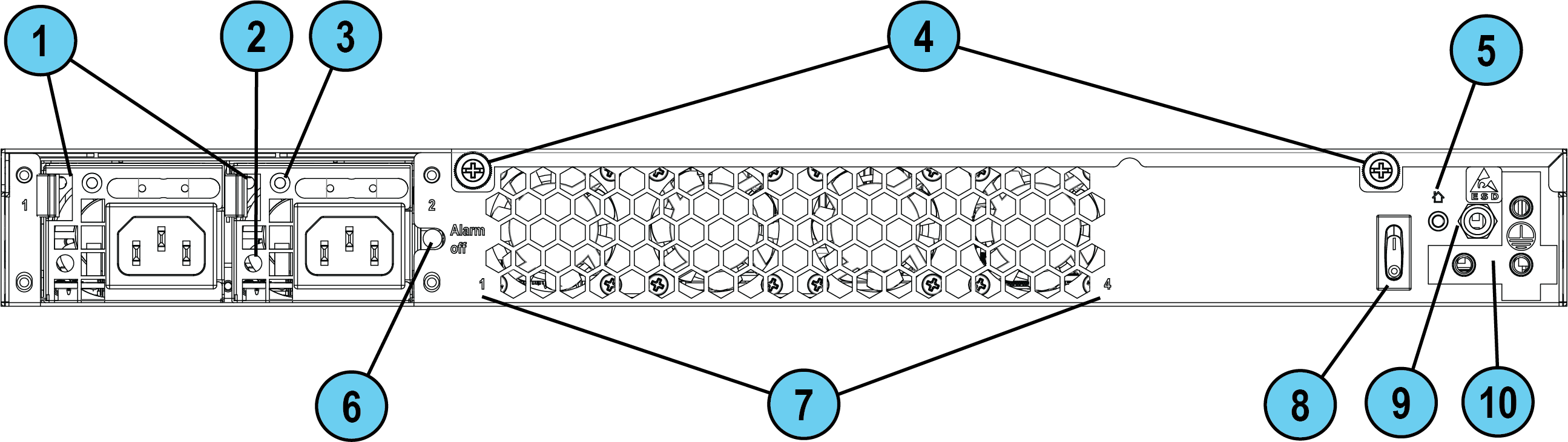
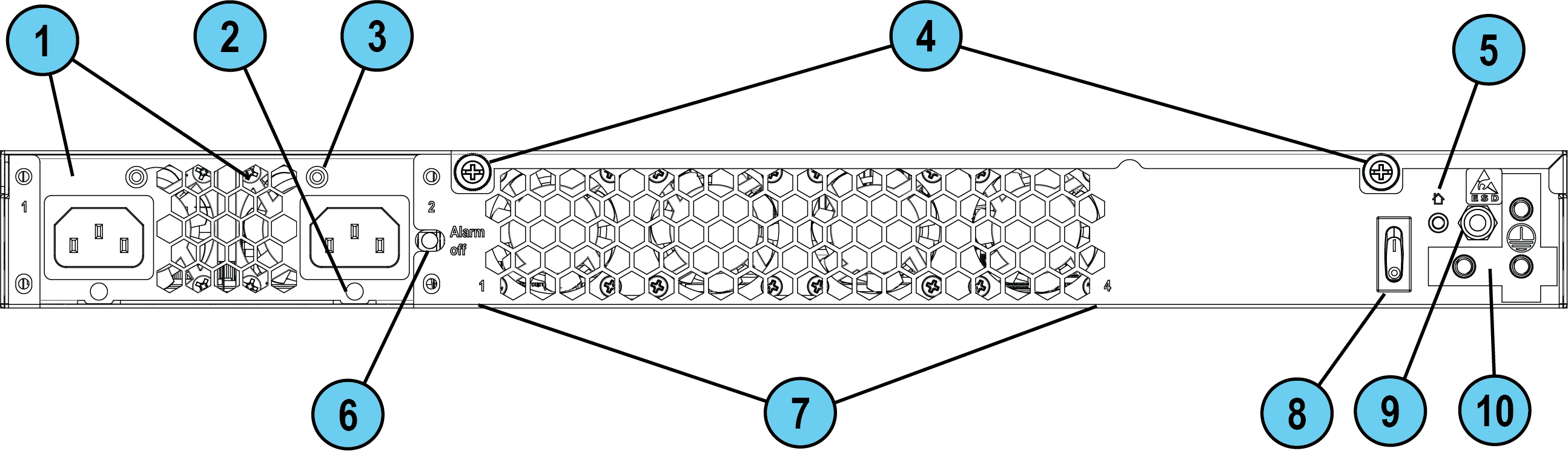
Diagrams for different appliance models:
|
9800 / 9700 / 9400 / 9300 |
9200 / 9100 |
|---|---|
|
|
|
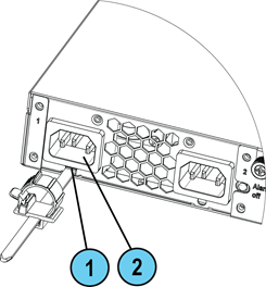
|
Item |
Description |
|---|---|
|
1 |
Restraint strip slot |
|
2 |
Power supply inlet |
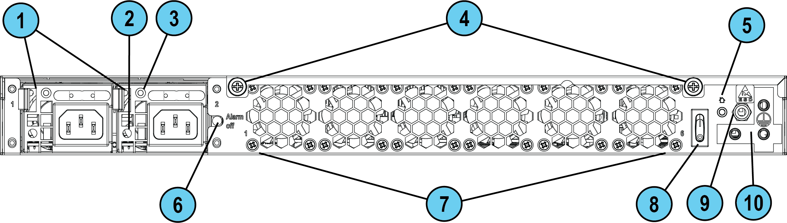
To install the power cable restraint:
-
If a power cable is connected to the power supply inlet, disconnect it.
-
Find the restraint strip slot on top of the power supply inlet.
-
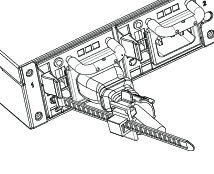
Make sure that the cable loop on the restraint faces the power supply inlet.
-
Insert the restraint strip anchor into the slot until it snaps and locks.
-
Connect the power cable to the power supply inlet.
-
Pull the restraint tab to the side to move the cable loop on the restraint strip.
-
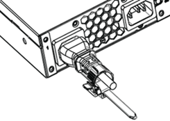
Move the cable loop until you can wrap it around the power cable as shown in the next figure.
-
Insert the open side of the cable loop into the loop slot until it is tight against the power cable.
Make sure the cable loop is secured and the power cable cannot be removed.
|
9800 / 9700 / 9400 / 9300 |
9200 / 9100 |
|---|---|
|
|
|
Lights Out Management
The Check Point Lights Out Management (LOM) card lets you use a dedicated management channel to remotely control Check Point appliances. Lights Out Management can also work when the appliance is turned off or does not respond. However, the appliance must be connected to a power source.
For more information about Lights Out Management, see the Lights Out Management (LOM) HTML5-based Card Administration Guide.
Dual Redundant BIOS
To ensure resilience in the event of a BIOS failure, appliances are equipped with dual redundant BIOS images.
If an appliance encounters a BIOS failure, it boots up from a recovery, read-only BIOS image that enables full functionality of the appliance.
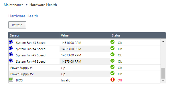
These notifications appear in the event of a BIOS failure:
-
The appliance's Alert LED on the front panel blinks red.
-
The Gaia Portal > Maintenance > Hardware Health page shows that the BIOS sensor is Invalid and its status is Off.
Example (from a 9800 appliance):
-
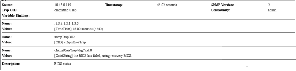
An SNMP trap message is sent (if the
biosFailuretrap was configured in the Gaia Portal or Gaia Clish).Example:
To recover from a BIOS failure, see sk108517 or contact Check Point Support. The appliance is fully functional until the BIOS recovery is completed. Note that it can take a few minutes for it to boot in BIOS recovery mode.
PSU Configuration and Monitoring
These are the supported PSU configurations for the appliance models and PSU types:
|
|
Important - All PSUs on an appliance must be of the same type: all AC or all DC. |
|
|
Important - When using DC PSUs, the DC power source must be reliably grounded. |
To monitor the PSUs in the CLI:
-
Connect to the command line on the appliance.
-
Log in to Gaia Clish.
-
Run:
show sysenv psExample output from a 9800 appliance:
Hardware Information

Name              Value   Unit      Type    Status   Maximum   Minimum
Power Supply #1   Up      Up/Down   Power   0        Up        Down
Power Supply #2   Up      Up/Down   Power   0        Up        Down
Where:
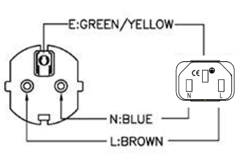
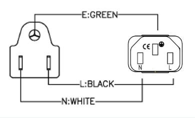
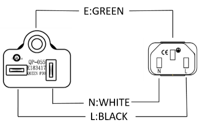
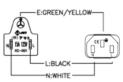
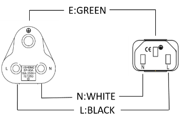
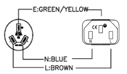
AC Power Cords
The supplied AC power cords are specific to the geographical region.
These are some of the available power cords.
|
Region |
Plug |
Connector |
Cable |
Diagram |
|---|---|---|---|---|
|
EU |
QP-004, 16A 250V~ |
QP-007, 10A 250V~ |
HO5VV-F 3G 0.75mm2 |
|
|
Australia |
QP-003, 10A 250V~ |
QP-007, 10A 250V~ |
HO5VV-F 3G 0.75mm2 |
|
|
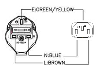
UK |
QP-026, 10A 250V~ |
QP-007, 10A 250V~ |
HO5VV-F 3G 0.75mm2 |
|
|
US |
QP-02, 10A 125V~ |
QP-007, 10A 125V~ |
SJT 18AWG 3C 105°C |
|
|
US |
QP-02, 15A 125V~ |
QP-007, 15A 125V~ |
SJT 14AWG 3C 105°C |
|
|
US |
QP-055, 15A 125V~ |
QP-007, 15A 125V~ |
SJT 14AWG 3C 105°C |
|
|
Japan |
QP-005, 10A 250V~ |
QP-007, 10A 250V~ |
HO5VV-F 3G 0.75mm2 |
|
|
India |
QP-013, 16A 250V~ |
QP-007, 10A 250V~ |
3INR 3G 0.75mm2 |
|
|
China |
QP-012, 10A 250V~ |
QP-007, 10A 250V~ |
VCTF 3G 2mm2 |
|
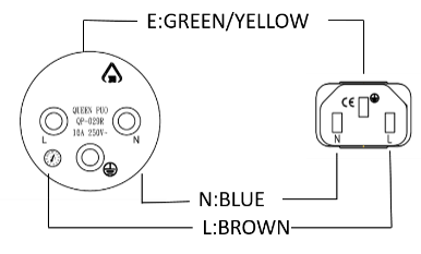
|
Israel |
QP-029R, 16A 250V~ |
QP-007, 10A 250V~ |
HO5VV-F 3G 0.75mm2 |
|
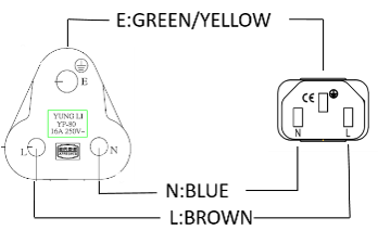
|
South Africa |
YP-80, 16A 250V~ |
QP-007, 10A 250V~ |
HO5VV-F 3G 0.75mm2 |
|
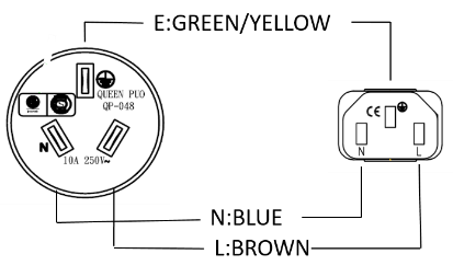
|
Argentina |
QP-048, 10A 250V~ |
QP-007, 10A 250V~ |
HO5VV-F 3G 0.75mm2 |
|


Replacing and Upgrading Components
The appliances have parts that you can easily replace to minimize downtime.
There are also components that you can install to upgrade the appliance.
These parts and components can be used with the appliance:
-
Telescopic rails
-
Line cards
-
Transceivers
-
AC and DC power supply units
-
Storage devices
-
System memory
-
Lights Out Management - In 9800 Base / 9700 Base / 9400 Base / 9300 Base / 9200 Base / 9100 Base appliances, the LOM Card is optional.
For more information about how to install these parts and components, see the appliance Home Page sk181698.
|
|
Warning - Unless directed to do so by Check Point Software Technologies Ltd., you are prohibited by warranty and support agreements to replace any parts. |
