Smart-1 7000-XL and Smart-1 7000-UL
Preparing the Appliance
Before you start to install or remove DIMMs, make sure:
-
You shut down the appliance and unplug the power cables.
-
The appliance is in a clean environment and on a level surface.
-
You can physically access and open the cover of the appliance.
-
You have the Check Point Memory Kit.
Important
-
To protect the appliance and the memory modules from electrostatic discharge, make sure that you are properly grounded before you touch these components.
-
We recommend that you use the grounding wrist strap that is included in the memory kit. The grounding plug on the rear of the appliance provides a chassis grounding point.
-
For more information, read the Health and Safety Information in the Getting Started Guide:
Smart-1 7000-XL / Smart-1 7000-UL Appliances Getting Started Guide
Memory Kit contents
-
QR code page - Installing and Removing Memory in Check Point Appliances
-
Memory DIMMs
-
ESD grounding strap (anti-static)
To prepare the appliance:
-
Shut down the appliance by one of these methods: from the Gaia Portal, through CLI commands, or quickly press and release the power switch.
Note - We do not recommend the use of the power switch as it results in a forced and immediate shut down.
-
Remove the power cords from the appliance.
-
Place the ESD strap on your wrist and attach the other end to a grounding point on the appliance.
-
Loosen the appliance cover screws.
-
Remove the top cover from the appliance.
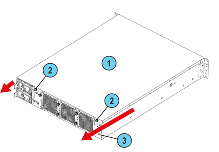
To remove the top cover:
-
Unscrew the cover screws (number 2 on the diagram below).
-
Pull the top cover back in the same direction the red arrows are pointing on the diagram.
-
Pull the cover up to remove it completely.
|
Item |
Description |
|---|---|
|
1 |
Appliance cover |
|
2 |
Appliance cover screws |
|
3 |
ESD grounding point |
About DIMM Sockets and the RAID Card Module
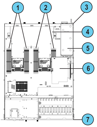
|
Item |
Description |
|---|---|
|
1 |
CPU0 DIMM sockets |
|
2 |
CPU1 DIMM sockets |
|
3 |
Appliance rear panel |
|
4 |
Air duct cover |
|
5 |
PSU unit |
|
6 |
RAID card module |
|
7 |
Appliance front panel |
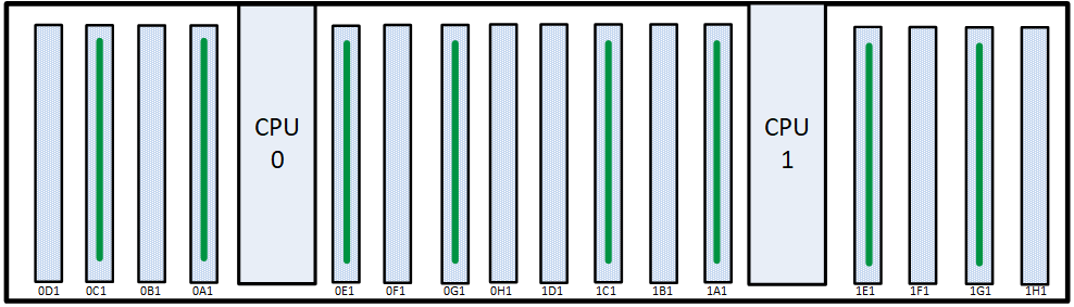
The memory sockets are situated to the left and right of the CPU units. Note - In the appliance configuration diagrams:
-
The view shown is always from above the appliance.
-
The front panel of the appliance is always at the bottom of the diagram.
Item
Description
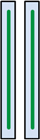
Memory socket with DIMM installed
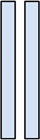
Memory socket without DIMM installed
Removing the RAID Card Module
If you need to handle a DIMM in a memory socket that is located between CPU1 and the PSU unit, you first need to remove the RAID card module.
|
|
Important - Make sure you have a magnetic screwdriver to remove the screws. |
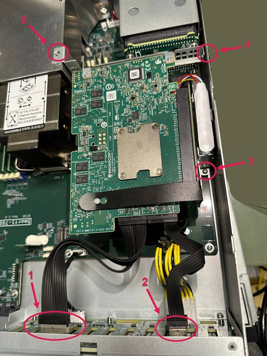
To remove the RAID card module:
-
Locate the RAID card module (see About DIMM Sockets and the RAID Card Module).
-
Disconnect the first SAS cable (1):
-
Put your thumb on top of the plastic connector.
-
Put your index finger on the on the clasp on the bottom of the connector.
-
Press and hold both fingers to unlatch the clasp.

-
Remove the plastic connector from its metal receptacle on the circuit board attached to the storage devices' enclosure.
-
-
Disconnect the second SAS cable (2):
-
Put your thumb on top of the connector.
-
Put your index finger on the on the clasp on the bottom of the connector.
-
Press and hold both fingers to unlatch the clasp.
-
Remove the plastic connector from its metal receptacle on the circuit board attached to the storage devices' enclosure.
-
-
Remove these screws:
-
Screw (3) that attaches the RAID card module to the bottom panel of the appliance.
-
Screw (4) that attaches the RAID card module to the side panel of the appliance.
-
Screw (5) that attaches the RAID card module to the air duct.
-
-
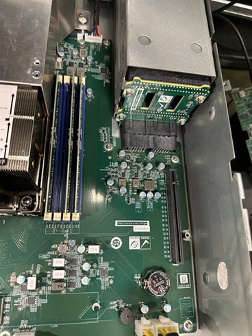
Grasp and hold the vertical circuit board that is parallel to the side panel, near screw (3).

-
Carefully pull the RAID card module up and out of its slot on the motherboard.
-
Place the RAID card module on a horizontal surface that does not conduct electricity (wood, paper, plastic) and cannot scratch the module.
You can now handle the unobstructed DIMMs located between CPU1 and the PSU.
Installing the RAID Card Module
After handling a DIMM in a memory socket that is located between CPU1 and the PSU unit, reinstall the RAID card module.
|
|
Important - Make sure you have a magnetic screwdriver to fasten the screws. |
To install a RAID card module:
-
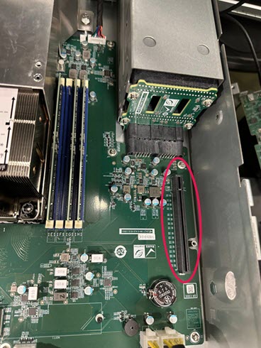
Locate the RAID card module slot on the motherboard.
-
Hold the RAID card module's vertical circuit board and align it with the side panel of the appliance and its slot on the motherboard.
-
Carefully push down on the RAID card module until it sits securely in the slot on the motherboard.
-
Fasten these screws:
-
Screw (5) that attaches the RAID card module to the air duct.
-
Screw (4) that attaches the RAID card module to the side panel of the appliance.
-
Screw (3) that attaches the RAID card module to the bottom panel of the appliance.
-
-
Connect the second SAS cable (2):
-
Put your thumb on top of the connector.
-
Put your index finger on the on the clasp on the bottom of the connector.
-
Press and hold both fingers on the connector.
-
Insert the plastic connector into its metal receptacle on the circuit board attached to the storage devices' enclosure until it snaps into place.
-
-
Connect the first SAS cable (1):
-
Put your thumb on top of the connector.
-
Put your index finger on the on the clasp on the bottom of the connector.
-
Press and hold both fingers on the connector.
-
Insert the plastic connector into its metal receptacle on the circuit board attached to the storage devices' enclosure until it snaps into place.
-
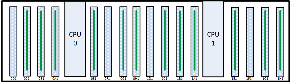
Smart-1 7000-XL Base and Smart-1 7000-UL Base Appliance DIMM Configuration
The Smart-1 7000-XL Base and Smart-1 7000-UL Base appliances have a default memory configuration of 256GB: 8 x 32GB.
As needed, replace faulty DIMMs with new ones. Make sure to place them in the DIMM sockets as shown in the diagram.
|
256GB Memory Configuration |
|---|
|
Top View |
You can upgrade to 384GB.
To upgrade to 384GB, use 12 x 32GB DIMMs. Make sure to place them in the sockets as shown in the diagram.
|
384GB Memory Configuration |
|---|
|
Top View |
Smart-1 7000-XL Plus and Smart-1 7000-UL Plus Appliance DIMM Configuration
The Smart-1 7000-XL Plus and Smart-1 7000-UL Plus appliances have a default memory configuration of 384GB: 12 x 32GB.
As needed, replace faulty DIMMs with new ones. Make sure to place them in the DIMM sockets as shown in the diagram.
|
384GB Memory Configuration |
|---|
|
Top View |
Removing DIMMs
|
|
Important - The appliance contains sharp metal parts such as the heat sink fin and bracket. Handle with care to avoid injury or damage the DIMMs. |
Make sure that you prepare the appliance before you remove DIMMs. For more information, see Preparing the Appliance.
To remove DIMMs from the appliance:
-
Remove the power cords from the appliance.
-
Place the ESD strap on your wrist and attach the other end to a grounding point.
-
Remove the RAID card module that covers the DIMMs located between CPU1 and the PSU. See Removing the RAID Card Module.
-
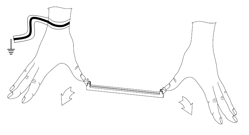
Press the two retaining clips on the DIMM outward.
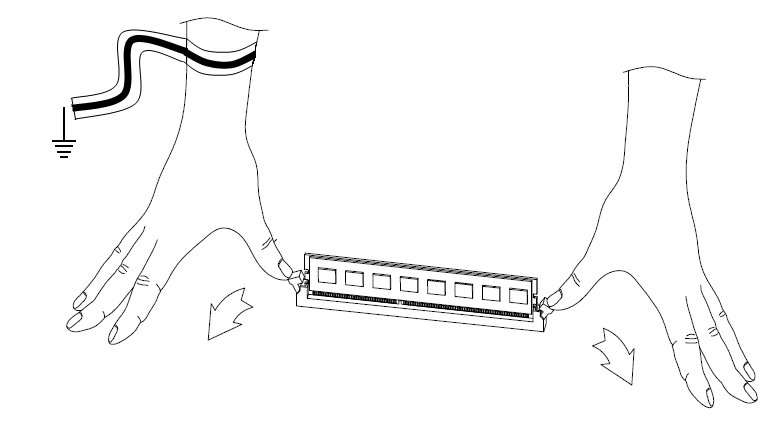
-
Carefully pull up the DIMM.

Important - Only touch the rear corners of the DIMM. Pressing on the heat sink or other DIMM components can damage the hardware.
If necessary, first pull up one end of the DIMM, and then the other to gradually release the DIMM from the contact pins.
Important - Make sure that there are no leftover or loose parts inside the appliance.
-
If you do not need to install any DIMMs:
-
Reinstall the RAID card module. See Installing the RAID Card Module.
-
Replace the appliance cover without tightening the appliance cover screws.
-
Connect the power cords to the appliance.
The appliance turns on.
-
Tighten the appliance cover screws to secure the cover on the appliance.
-
Installing DIMMs
|
|
Important - The appliance contains sharp metal parts such as the heat sink fin and bracket. Handle with care to avoid injury or damage the DIMMs |
To install DIMMs in the appliance:
-
Find the DIMM slots on the system board.
-
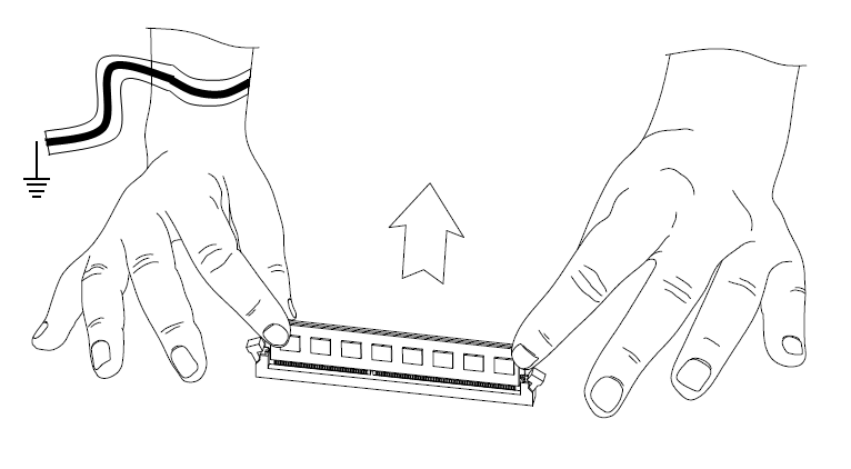
Press outward on the two white retaining clips.
-
Align the new DIMM above the socket.
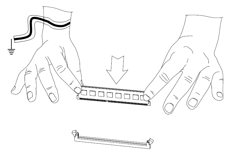
The top of the DIMM is smooth. The bottom edge has two different-length sets of contacts which connect to the slots on the socket.
Important:
-
Only touch the top corners of the DIMM. Pressing on the heat sink or other DIMM components can damage the hardware.
-
DIMMs are not symmetrical. Use the hole in the DIMM to guide the DIMM into the raised tooth in the slot.
-
-
Press the new DIMM into the socket until it clicks into position.
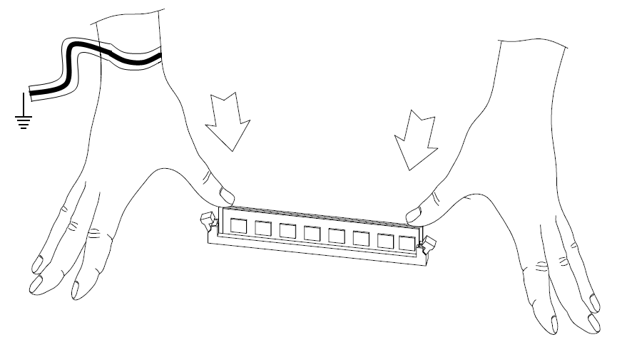
The retaining clips move into the lock position as you press the DIMM into position.
-
Do steps 1 - 4 again for the other DIMMs.
-
Make sure that there are no leftover or loose parts in the appliance.
-
Make sure the DIMM(s) are installed correctly.
-
Reinstall the RAID card module. See Installing the RAID Card Module.
-
Replace the appliance cover without tightening the appliance cover screws.
-
Connect the power cords to the appliance.
The appliance turns on.
-
Place and tighten the appliance cover screws to secure the cover on the appliance.
Verifying the Memory Configuration
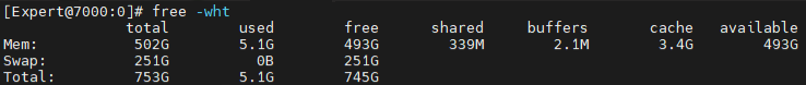
To see the memory amount in the Expert mode:
Run:
|
|
Example output from a Smart-1 7000-UL Plus appliance with 512GB of memory:
|
|
Note - The amount of installed memory appears in the Mem row in the total column. |

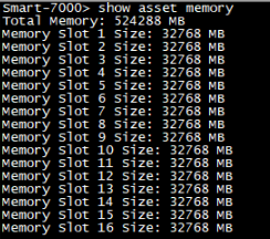
To see the populated memory slots in Gaia Clish:
-
Run:
show asset memoryExample output from a Smart-1 7000-UL Plus appliance with 512GB of memory:
-
Make sure the value in the Total Memory shows the installed memory.
|
|
Note - The “Memory Slot Number” is an ordinal count of DIMMs and does not correspond to the slot numbering shown in the motherboard DIMM configuration layout diagram. |
To view DIMM hardware details through the LOM Card:
See the Hardware Inventory section in the Lights Out Management (LOM) HTML5-based Card Administration Guide.