6000/7000 Appliances Hardware
Front Panel
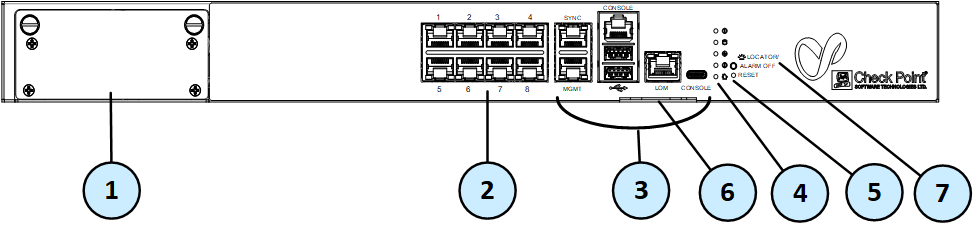
6200 Base

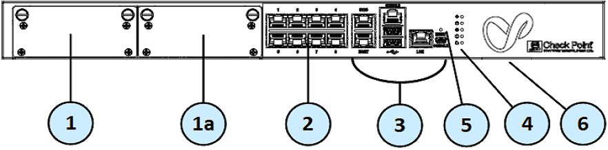
6200 Plus/Turbo and 6400 Base/Plus
6500

6600 Base/Plus and 6700 Base/Plus

6800
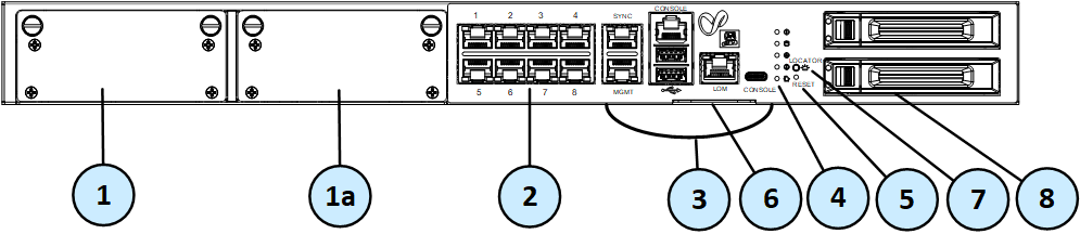
6900 Base/Plus and 7000 Base/Plus
Front Panel Ports

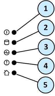
Front Panel System LEDs
System power, storage device activity, power supply status, alert, and location.
|
Item |
Icon |
Component |
Description |
|---|---|---|---|
|
1 |
|
System power |
|
|
2 |
|
Storage device activity |
|
|
3 |
|
Power supply status |
Note - 6200 Base appliances - do not have this system LED. |
|
4 |
|
Alert |
|
|
5 |
|
Location beacon |
Note - You can turn off the Location beacon LED from the Locator button, Gaia Portal, or Gaia Clish. |


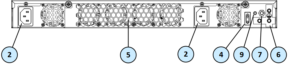
Rear Panel
6200 Base

6200 Plus/Turbo and 6400 Base/Plus
6500

6600 Base/Plus, 6700 Base/Plus, and 6900 Base/Plus

6800

7000 Base/Plus

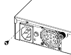
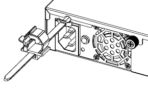
Using the Power Cable Restraint Strip on 6200 and 6400 Appliances
On 6200 and 6400 appliances, you can use the power cable restraint to prevent accidental removal of the power cable.

|
Item |
Description |
|---|---|
|
1 |
Restraint anchor |
|
2 |
Cable loop |
|
3 |
Restraint strip tab |
|
4 |
Restraint strip |
To install the power cable restraint strip:
-
If a power cable is connected to the power supply inlet, disconnect it.
-
Unscrew the screw directly above the power supply inlet.
-
Make sure the cable loop on the restraint strip faces the power supply inlet.
-
Insert the restraint strip anchor into the slot and screw it in until it locks.

-
Connect the power cable to the power supply inlet.
-
Move the cable loop on the restraint strip.
-
Move the cable loop until you can put it around the power cable.
-
Insert the open side of the cable loop into the loop slot until it is tight against the power cable.
-
Make sure the cable loop is secured and the power cable cannot be removed.

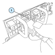
Using the Restraint Clip on 6500, 6600, 6700, 6800, 6900, and 7000 Appliances
The 6500, 6600, 6700, 6800, 6900, and 7000 appliances have a power cable restraint clip attached to the power supply unit (PSU). Use the restraint clip to prevent accidental removal of the power cable.
To secure the restraint clip on the power supply cable:
-
Make sure the restraint clip is in the open position (upward).
-
Connect the power supply cable to the power supply inlet on the PSU.
-
Push down on the restraint clip to close it and secure the power supply cable.


|
Item |
Description |
|---|---|
|
1 |
Restraint clip in the open position (upward) |
|
2 |
Restraint clip in the closed position |
Lights Out Management
The Check Point Lights Out Management (LOM) card lets you use a dedicated management channel to remotely control Check Point appliances. Lights Out Management can also work when the appliance is turned off or not responding.
Lights Out Management is an optional feature on the 6200 Base, 6400 Base, 6500, 6600 Base, 6700 Base, 6900 Base, and 7000 Base appliances.
It is included by default with the 6200 Plus/Turbo, 6400 Plus, 6600 Plus, 6700 Plus, 6800, 6900 Plus, and 7000 Plus appliances.
For more about using Lights Out Management, see the Lights Out Management Administration Guide.
Dual Redundant BIOS
To ensure resilience in the event of a BIOS failure, 6000 and 7000 Appliances are equipped with dual redundant BIOS images.
If an appliance encounters a BIOS failure, it will boot up from a recovery, read-only BIOS image that enables full functionality of the appliance.
These notifications are shown in the event of a BIOS failure:
-
The appliance's Alert LED on the front panel will blink red.
-
The Gaia WebUI Hardware Health window shows that the BIOS sensor is Invalid and its status is Off.
-
An SNMP trap message (if the biosFailure trap was configured in the WebUI or through clish).

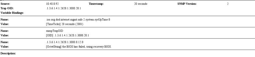
To recover from a BIOS failure, see sk108517 or contact Check Point support. The appliance is fully functional until the BIOS recovery is completed.

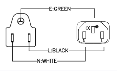
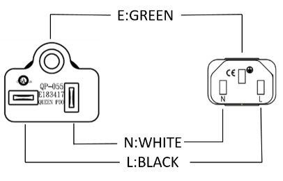
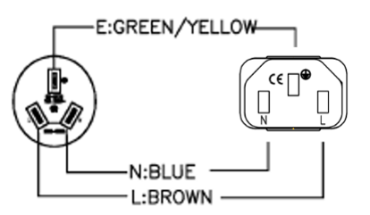
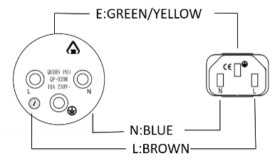
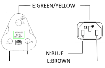
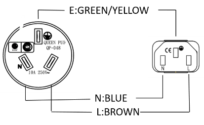
AC Power Cords
The supplied AC power cords are specific to the geographical region.
These are some of the available power cords.
|
Region |
Plug |
Connector |
Cable |
Diagram |
|---|---|---|---|---|
|
EU |
QP-004, 16A 250V~ |
QP-007, 10A 250V~ |
HO5VV-F 3G 0.75mm2 |
|
|
Australia |
QP-003, 10A 250V~ |
QP-007, 10A 250V~ |
HO5VV-F 3G 0.75mm2 |
|
|
UK |
QP-026, 10A 250V~ |
QP-007, 10A 250V~ |
HO5VV-F 3G 0.75mm2 |
|
|
US |
QP-02, 10A 125V~ |
QP-007, 10A 125V~ |
SJT 18AWG 3C 105oC |
|
|
US |
QP-02, 15A 125V~ |
QP-007, 15A 125V~ |
SJT 14AWG 3C 105oC |
|
|
US |
QP-055, 15A 125V~ |
QP-007, 15A 125V~ |
SJT 14AWG 3C 105oC |
|
|
Japan |
QP-005, 10A 250V~ |
QP-007, 10A 250V~ |
HO5VV-F 3G 0.75mm2 |
|
|
India |
QP-013, 16A 250V~ |
QP-007, 10A 250V~ |
3INR 3G 0.75mm2 |
|
|
China |
QP-012, 10A 250V~ |
QP-007, 10A 250V~ |
VCTF 3G 2mm2 |
|
|
Israel |
QP-029R, 16A 250V~ |
QP-007, 10A 250V~ |
HO5VV-F 3G 0.75mm2 |
|
|
South Africa |
YP-80, 16A 250V~ |
QP-007, 10A 250V~ |
HO5VV-F 3G 0.75mm2 |
|
|
Argentina |
QP-048, 10A 250V~ |
QP-007, 10A 250V~ |
HO5VV-F 3G 0.75mm2 |
|


Replacing and Upgrading Components
The 6000 and 7000 appliances have parts that you can easily replace to minimize downtime. There are also components that you can install to upgrade the appliance. These are the parts and components that can be used with the appliance:
-
Telescopic rails
-
Line cards
-
Transceivers
-
AC and DC power supply units - For 6500, 6600, 6700, 6800, 6900, and 7000 appliances only
-
System memory
-
Lights Out Management
-
Storage devices - For 6800, 6900, and 7000 appliances only
For more information about installing these parts and components, see the appliance home page.
Unless directed to do so by Check Point technical support, you are prohibited by warranty and support agreements from replacing any parts.